“Send the PCB files” leaves several choices open. A supplier may need layer images, component or net attributes, job-level metadata, drill/rout data, or a structured PCB manufacturing description. Those roles may be split across different files and specifications. Identify the requested information and receiver input before treating a format name or support statement as a complete handoff.
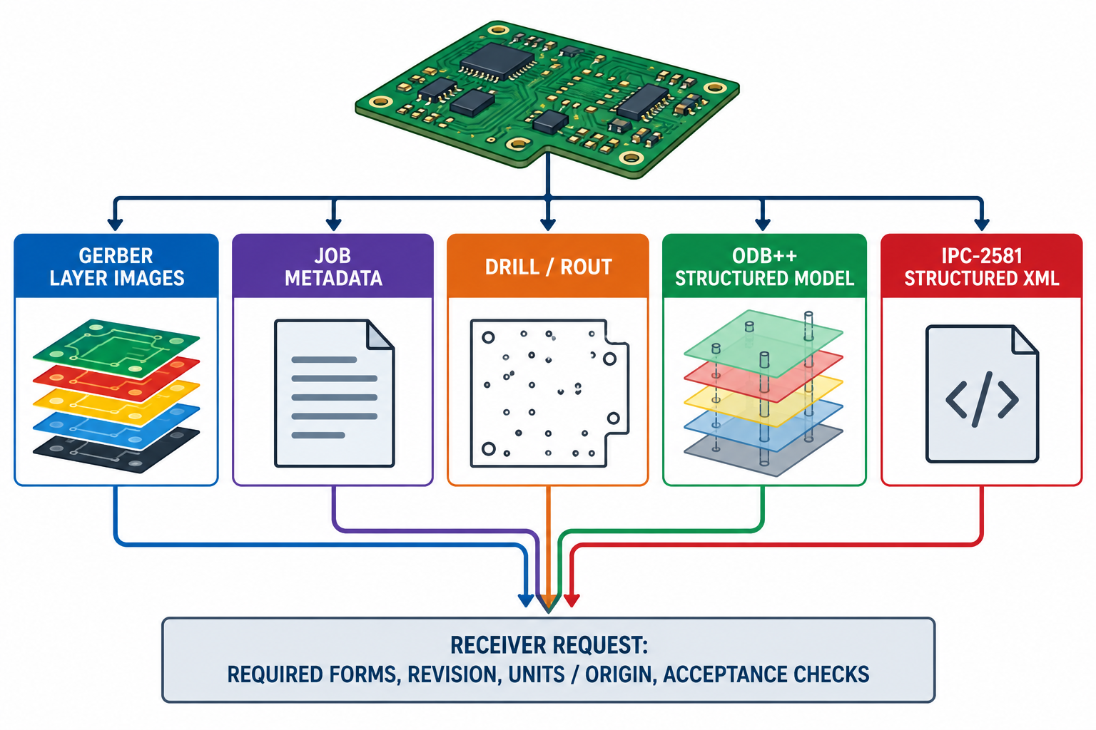
Separate mechanical coordination from fabrication data
A 3D board or enclosure representation can support fit and placement work. It is not a substitute for the electrical and fabrication information needed to make or assemble a board. Conversely, a fabrication package does not necessarily carry the editable source design or a complete enclosure context.
Start by recording the board and selected population/configuration state, the job purpose, and the information the recipient needs. Electrical design content—such as net relationships and component population—has its own requirements. This article compares representation roles; it does not establish that a particular exporter includes them or that a manufacturing process accepts them.
Compare the representation roles
| Role | Representation and cited scope | What it can describe | What to request or verify |
|---|---|---|---|
| Layer artwork and scoped attributes | Gerber Layer Format Revision 2026.05 | Two-dimensional PCB fabrication layers. The specification defines .N net-name and .P component-pin attributes; together on a component pad they express a pad-to-net entry in its CAD-netlist model. |
Required image layers and their functions; whether the selected output includes the needed attributes and component data; units and coordinate alignment. An absent attribute does not prove that the underlying design has no such relationship. |
| Job-level metadata | Gerber Job File JSON Schema associated with Revision 2023.06 | A separate JSON object with fields for job context such as project identity, stackup, design rules, and attributes associated with files. | Whether the job file is required, which schema revision is expected, which output files it describes, and whether those files are present and correspond to the selected board. The schema is not layer geometry or a package-closure result. |
| Drill and routed slots | Gerber drill/rout data or a requested NC dialect such as XNC | A separate representation of drill holes and routed slots. Ucamco lists XNC Revision 2021.11 on its downloads page; that specification defines PCB CAD-to-CAM exchange. | The receiver’s accepted format/dialect, units, origin and axes, plated/non-plated grouping, and required resolution. XNC is described as CAD-to-CAM input, not a machine-specific output. |
| Structured multi-file model | ODB++Design Release 8.1 Update 3, February 2021 | A directory-based product model with steps, layers, EDA data, properties, and net connectivity; its cited eda/data format requires a UNITS directive. |
Exact ODB++ revision, required model-tree elements, units, selected design state, exporter scope, receiver version, and the full directory tree. Release 8.1 Update 3 is the cited document, not a claim that it is the latest revision. |
| Structured XML exchange | IPC-2581 at a specifically agreed revision | The Consortium describes IPC-2581 as PCB and assembly manufacturing-description data and a transfer methodology. | Exact revision, corresponding XSD, sender/receiver support, required content, and the downstream acceptance checks. No specific revision or product pair is established by the cited sources. |
Placement coordinates, a bill of materials, and a standalone netlist may be separate outputs. List each one the recipient requires; Gerber component or net attributes do not establish that a separate placement, BOM, or netlist file is included.
These options are not a ranking or a set of equivalent substitutes. A handoff can require more than one representation—for example, layer artwork plus a separate job file and drill/rout output. ODB++ and IPC-2581 have their own structured information models; do not assume that a requested structured form makes companion data unnecessary without checking the receiver’s requirements.
Treat revisions and settings as part of the request
Ucamco’s downloads page, checked on 12 October 2026, lists Gerber Layer Format Revision 2026.05, the Job File schema, and XNC Revision 2021.11 as separate documents. The XNC PDF identifies Revision 2021.11. Record the exact revision requested and check the official listing again when current status matters. The specification describes holes and routed slots exchanged from PCB CAD to CAM; this does not make the file a machine-ready program or establish any receiver’s dialect support.
Product settings can change the file set and declarations a sender creates. For example, the KiCad 10.0 manual documents Gerber X2 attributes and an optional .gbrjob; drill output may use Excellon or Gerber X2, and its options include units, origin, and plated/non-plated file grouping. The manual also cautions that particular CAM compatibility choices depend on manufacturer requirements. These are KiCad 10.0 controls, not a generated-file inspection, a recommendation for every job, or a claim about another release.
Keep schema validation in its lane
For IPC-2581, the Consortium says to validate against the XSD corresponding to the specific revision being checked. That establishes schema conformance to the selected XSD. The Consortium explicitly says this does not verify design-data correctness, completeness, or manufacturability. No revision-specific XSD inventory or validation result is established here.
The same separation applies to other forms. A schema describes permitted structure; a product support declaration describes an implementation claim; a generated package must still be inspected for the required files, selected board state, units and payload. The receiver’s actual interpretation and acceptance require their own checks.
Make a receiver-specific representation request
Use a request record that names the needed information rather than only a file suffix:
purpose: "fabrication | assembly | other"
board_and_selected_state: "..."
required_data:
  layer_images_and_attributes: "..."
  job_metadata: "required | not required | confirm"
  drill_rout_format_and_dialect: "..."
  structured_description: "none | ODB++Design | IPC-2581"
format_and_schema_revisions: "..."
units_origin_and_axes: "..."
required_companion_files: []
container_or_directory_tree: "..."
exporter_product_release_and_settings: "..."
receiver_product_release_and_accepted_input: "..."
validation_and_acceptance_checks: []
Use unknown where a sender or recipient has not answered yet. Confirm the receiver’s requested form and revision before choosing export controls, then inspect the resulting file set against that request.
For the electrical payload and board/enclosure requirements, use the electrical-design exchange scope. For production and process meaning, continue to manufacturing and quality handoffs. For a named product pair, check its ecosystem route; for schema scope, repeatable checks, and recipient acceptance, see validation and long-term reuse.
Key points
- Gerber layers, Gerber Job File metadata, drill/rout output, ODB++Design, and IPC-2581 have distinct roles and revisions.
- A file list, directory, ZIP, or format label does not establish that the requested PCB data is present or aligned.
- KiCad controls, format schemas, and support declarations do not prove generated-file correctness or recipient acceptance.
- IPC-2581 XSD validation is revision-specific and does not establish correctness, completeness, or manufacturability.
- Specify the receiver’s required forms and checks before relying on a fabrication handoff.