A CAD-to-CNC exchange crosses more than one boundary. Design data may become CAM input, CAM data may become a controller-specific program, and a shop may add setup or machine context at each stage. An imported solid can be a useful starting point without carrying machining intent or executable output.
Keep the boundaries separate
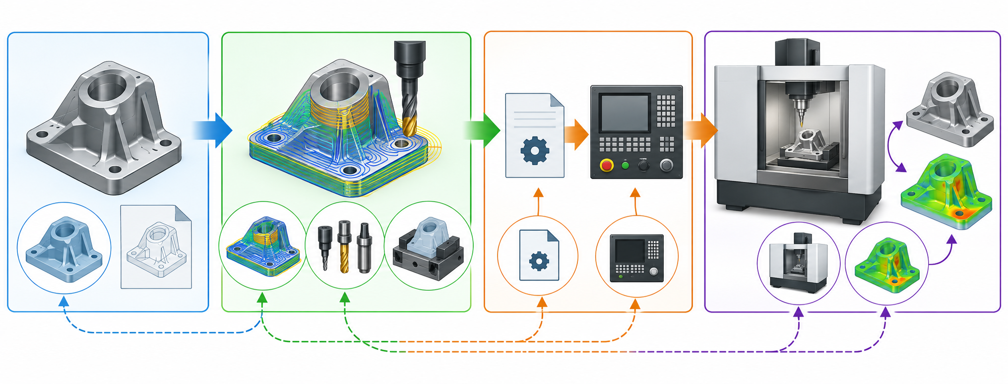
The route is easier to assess when it is written as three questions:
design definition → CAM/process planning → controller or machine interface
Each arrow is a separate interoperability claim.
- Design definition → CAM: Can the recipient use the shape, units, orientation, topology, datums, features, and relevant semantic information?
- CAM/process planning → controller: Does the next system receive process information, working steps, machine functions, and the context needed for its own output?
- Controller interface → machine: Does the selected postprocessor and controller configuration produce an accepted program for that machine?
Evidence for one arrow does not establish the others. In particular, CAD interchange does not prove portable toolpaths or controller-ready NC code.
What the process-data models clarify
ISO 14649-10 describes general process data at the interface between a programming system—including CAM or shop-floor programming—and a computerized numerical controller. Its abstract identifies geometric and technological information, workplans, working steps, NC functions, a workpiece, and the basis for operation definitions. It also says that technology-specific definitions and representations are provided through other resources or parts; the general schema is not a complete machining route by itself.
ISO/TS 14649-201 adds technology-specific machine-tool description data for manufacturing and machine characteristics. Its examples include CNC part programming, process planning, machining simulation, and analysis of expected machining time and machine-tool energy use. These are data-model scopes and application examples, not evidence that a particular product exchanges or executes them.
A historical NIST STEP-NC testing paper adds a useful validation boundary: file syntax, application structure and constraints, and correctness for the given input are separate checks. Its CNC test model also considers the exchanged STEP-NC data alongside tooling, setup, and processing specifications, then compares the machined result with the controlling CAD model and expected values. This is a testing model, not evidence of a current commercial route, but it explains why a conforming file and a usable manufacturing result are different claims.
Classify each item in the handoff
| Item | Treat it as | Verify before calling it preserved |
|---|---|---|
| Design geometry | A possible CAM input | Units, orientation, topology, faces, gaps, feature recognition, and any required datums or references. |
| Machining features | A semantic convenience or process input when the route supports them | Which feature types are recognized, in which direction, release, and profile; do not infer support from a neutral file name. |
| Workplans and working steps | Process intent or sequence | Whether the recipient imports the steps, maps them to its own operations, or rebuilds them. |
| Tools, fixtures, and setup/orientation | Resource and machine context | Whether the target has equivalent resources and whether the transferred values are authoritative or only planning context. |
| Machine characteristics | Recipient-specific manufacturing-resource data | Machine technology, configuration, controller assumptions, and the versioned implementation on both ends. |
| Toolpaths and postprocessed NC | Derived, controller-bound output unless the route explicitly proves otherwise | Postprocessor, controller dialect, machine configuration, and a controlled recipient check. |
| Inspection references | A separate quality link | Whether characteristics and identifiers still point to the same design definition after CAM preparation. |
A bounded example of machine context and generated output
Autodesk Fusion Manufacture documentation separates a machine definition from the NC program generated from selected operations. A machine definition can describe capabilities and kinematics and link a postprocessor or machine model; the NC Program tool uses a selected post to produce controller-specific NC code. Fusion can also generate a setup sheet with context such as the work coordinate system, stock and finished-part size or orientation, tools, and estimated cycle time.
These are Fusion-specific examples of configuration and generated deliverables, not portable CAM-interchange rules. A setup sheet is supporting documentation, not evidence that the recipient has editable operations or a matching machine, post, or controller. Identify which items are transferred or regenerated, then verify the actual output against the target machine and acceptance process.
Keep configuration, tools, and simulation companions distinct
Other manufacturing resources have their own exchange boundaries. Fusion’s configuration documentation associates manufacturing setups and toolpaths with the active design configuration; updating that configuration can make its toolpaths out-of-date. Record which configuration a manufacturing plan uses and whether dependent operations need regeneration. That status is Fusion-specific and does not imply that a neutral CAD file carries the setup or toolpaths.
Fusion’s tool-library documentation also has different import and export lists, and CSV export omits expressions defined in the library. Check the transfer direction and inspect the resulting tool data; a tool-library file does not establish that the recipient has matching tool geometry, machine context, or post assumptions. A documented FeatureCAM-to-VERICUT add-in provides another bounded example: its project includes NC output, tool and model/stock data, clamp/holder folders, settings, and a log, and Autodesk specifies FeatureCAM Ultimate for that add-in. This describes one product integration package, not independent validation of the imported project or acceptance by a machine.
Decide what may be regenerated
Regeneration is acceptable when the handoff names it as part of the route and the regenerated result is checked. For example, a recipient may be expected to rebuild operations from transferred geometry, select local tools, create a setup, or postprocess a plan for its controller. That is a different result from preserving the original operation sequence or toolpath.
Document regeneration explicitly:
- Transferred and authoritative: the design revision, critical dimensions or characteristics, and any process element the receiving party is required to use unchanged.
- Transferred as context: candidate features, operation hints, setup orientation, tooling references, or simulation data that help the recipient but do not replace its own verification.
- Regenerated by the recipient: CAM operations, toolpaths, posts, local resource bindings, or other outputs the route deliberately recreates.
- Checked after regeneration: geometry, stock or setup assumptions, identifiers, revision, and the downstream acceptance evidence required for the job.
Do not silently regenerate anything whose loss changes the design definition, inspection basis, or agreed production intent. If the source does not establish whether a process element is preserved, treat it as unresolved until the named sender, receiver, direction, release, and profile are checked.
A sheet-metal flat pattern is a separate 3D-to-2D fabrication derivative. Its selected profile, bend indicators, units, layers, and recipient interpretation need their own checks; they do not establish that CAM operations, machine context, or controller output were transferred. See Sheet-Metal Flat-Pattern Handoffs for that focused brief.
A handoff brief for CAM/CNC work
Give the recipient a short, explicit brief containing:
- Source system and design revision.
- Destination CAM system, controller, and relevant releases.
- Transfer representation and direction.
- Required geometry, units, orientation, datums, and semantic information.
- Process information that is transferred, regenerated, or intentionally not included.
- Tool, fixture, setup, machine, and postprocessor dependencies.
- Items that remain authoritative after regeneration.
- Checks that make the result acceptable for the stated manufacturing task.
For the representation and version questions behind this brief, see Formats, Profiles, and Translators. For a source-to-destination route, use Ecosystem Routes and Collaborative Exchange. For acceptance evidence, see Validation, Exchange Control, and Long-Term Reuse.
These links lead to adjacent categories. A real route still needs product-specific evidence; ISO process-data scope alone does not demonstrate a named CAM, postprocessor, controller, or shop-floor implementation.