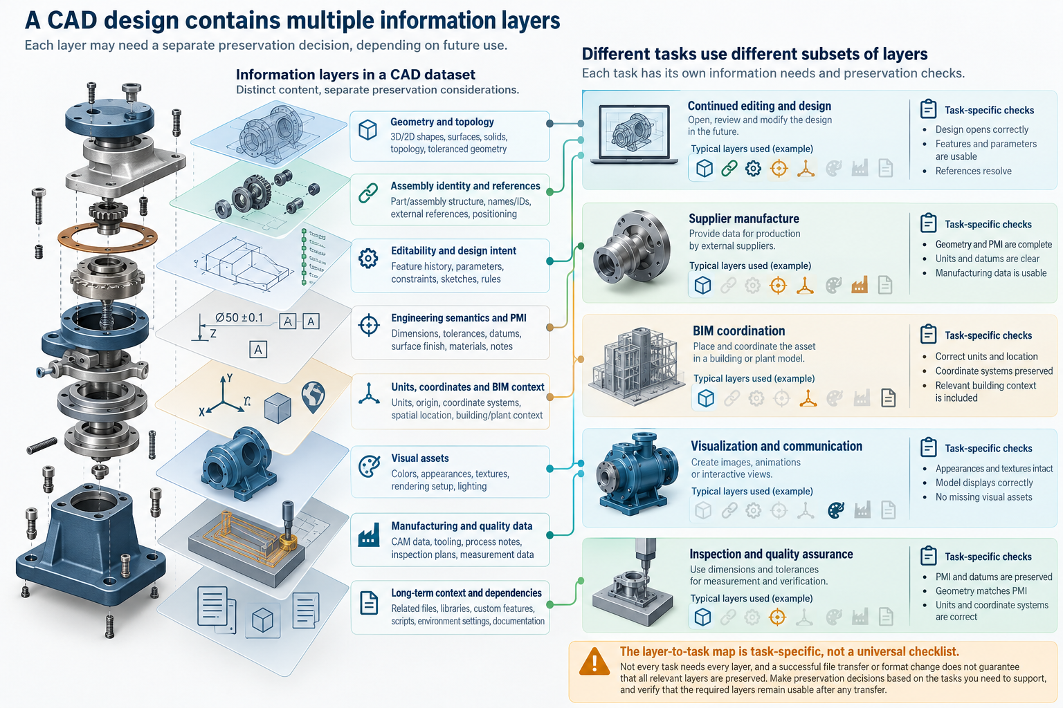
A design transfer does not preserve “the model” as one indivisible thing. It may preserve a shape while losing assembly identity, retain annotations as graphics without usable meaning, or create a visually convincing scene that no longer supports engineering edits. A preservation map makes those distinctions visible before a route is selected.
LOTAR’s long-term archiving and retrieval material separates process requirements from domains such as explicit geometry, assembly structure, graphic PMI, semantic PMI, and product-management data. Quality information can also extend beyond shape: QIF describes a domain that can include geometry, PMI, measurement plans, resources, and results. These are examples of why the payload must be mapped to the receiving task.
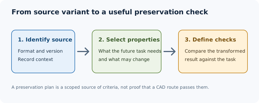
Long-term use adds information around the payload. CCSDS 653.0-M-1 separates the content data object from representation information such as structure, semantics, and software dependencies. It also identifies reference, provenance, context, fixity, access rights, package description, packaging, and potential future uses as information areas that may matter when data must remain understandable and trusted. For a CAD map, translate those areas into concrete questions about format definitions, dependent software, source and version context, integrity checks, access, and the future task. This is preparation guidance, not evidence that a particular CAD package preserves any of those layers. NARA says its format- and version-specific digital-design Preservation Plans identify significant properties that can serve as test criteria. Their scope reflects NARA’s holdings, risk assessment, and tools; use them as a prompt for task-specific properties, not as a universal CAD checklist or route result.
LOTAR’s 2025 publication notice gives a related scope boundary: its revised EN9300-100 covers general long-term archiving concepts for 3D CAD, while EN9300-210 addresses definition and validation of “as-designed” product structures and associated metadata. The notice summarizes standards scope rather than route conformance or acceptance, so use it to identify map rows, not to claim that a transfer satisfies them.
The layer map
Use the following as a candidate inventory. It is not a universal checklist; mark layers that do not matter to the actual exchange as not applicable.
| Information layer | Ask what must survive | Typical downstream reason | Evidence to request |
|---|---|---|---|
| Geometry, topology, or mesh | Which shape representation must survive—exact geometry, topology, tessellation, or an intentional combination—and what variation is acceptable? | Design review, machining, simulation input, printing, measurement, or visual output. | A scoped geometric comparison, topology/mesh checks, units, tolerances, and repair findings. |
| Product structure and identity | Do assemblies, occurrences, versions, configurations, substitutions, names, identifiers, and external shape/document references still mean the same thing? | Assembly coordination, procurement, service, change tracking, or later retrieval. | A structure comparison, dependency manifest, identity rules, and configuration coverage. |
| Editability and design intent | Can the recipient perform the named edits, and what happens on rebuild? | Continuing design work rather than one-time consumption. | Tests of the required editing operations, parameters, constraints, feature behavior, and rebuild outcome. |
| Engineering semantics and documentation | Do PMI, annotations, drawings, materials, engineering-property values and their validity conditions, classifications, and metadata remain usable rather than merely visible? | Supplier delivery, design definition, inspection, or handoff documentation. | Semantic checks, drawing/annotation review, metadata comparison, and source/destination interpretation. |
| Electrical/electronic design information | Which assembly, interconnect, packaging, device, or supplier information does the receiving task need? | Design analysis, manufacturing planning, or supplier handoff when electrical/electronic design is in scope. | Name the required data and associations, then verify them for the selected source, receiver, and task; a standard’s scope does not establish implementation support. |
| Spatial and BIM context | Are units, axes, transforms, coordinates, schemas, and information requirements correct? | Coordination, placement, model federation, quantity work, or building information exchange. | Coordinate and unit checks, model-view or schema scope, placement comparison, and information-requirement review. |
| Visual scene and asset data | Do materials, textures, lighting, cameras, animation, composition, and dependencies produce the intended scene? | Rendering, visualization, review, or asset reuse. | Image/scene comparison, asset manifest, path-resolution check, and approved visual criteria. |
| Manufacturing and quality data | Do process plans, resources, inspection requirements, measurements, and quality results needed downstream remain available—and are plans kept distinct from executed results? | CAM/CNC, fabrication, additive, metrology, or quality acceptance. | Task-specific process checks, measurement/inspection comparison, and an accountable acceptance decision. |
The rows overlap in real projects. A mesh can be the required production representation and an unacceptable substitute for editable solid geometry. A drawing may carry information that is not present as semantic PMI. Record the distinction rather than treating one layer as a proxy for another.
Separate representation, tolerance, and acceptance
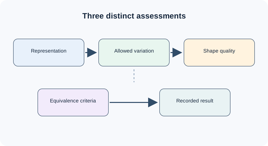
Geometry, allowable shape variation, measured quality, and equivalence are related but separate questions. ISO 10303 names geometric and topological representations separately from shape-variation tolerances, shape-quality criteria and inspection results, and context-dependent equivalence criteria. These scope descriptions do not establish that a route carries the items, and they provide no universal tolerance or acceptance threshold.
| Question | What to name in the map |
|---|---|
| What representation must arrive? | Exact geometry, topology, tessellation, or a defined combination. Part 42’s scope distinguishes these and excludes several other concerns, including assemblies and geometric tolerances. |
| What variation is allowed? | The relevant dimensions, datums, and size, location, or orientation tolerances; shape fidelity alone does not answer this. |
| How will quality be assessed? | Criteria, measurement requirements, assessment specifications, or inspection results that matter to the receiving task. |
| What counts as equivalent? | Application-specific comparison criteria, inspection requirements, and thresholds selected by the responsible project; no universal algorithm or threshold is implied here. |
For annotated models and assemblies, keep the assessed product data and configuration, the equivalence criteria and inspection requirements, and the recorded inspection result distinct. The published ISO module summaries describe these as separate information scopes, including assembly relationships and whole-assembly geometry; they do not supply project-specific criteria or establish that a transfer preserved them.
Add domain-specific context only when it matters
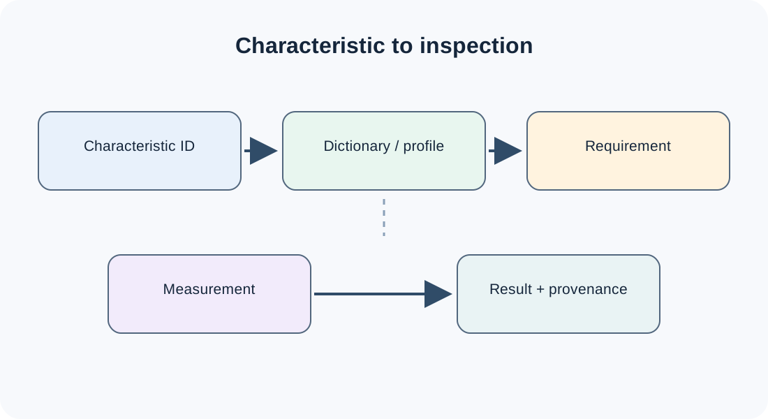
Some exchanges also depend on material or other engineering-property values and the conditions, precision, or uncertainty attached to them; product-state history; support and management context; or process-plan relationships and resources. Systems-engineering behavior, simulation baselines or parameter variants, test results, or API/domain-model data may matter when those are part of the stated transfer. Ask for these layers only when the receiving task needs them. A standard that represents a process plan does not show that the plan was executed, and a standard’s schema does not prove an implementation carries it. For inspection or traceability work, ask whether product-characteristic and verification identities must remain linked. If characteristic values travel as system-to-system master data, specify the dictionary authority and profile as well as the message’s syntax, semantic encoding, and data-specification checks; those requirements do not establish accuracy, provenance, or CAD-route support.
Map layers to a task
The required set depends on what happens after the transfer:
| Downstream objective | Likely required layers | Questions to resolve |
|---|---|---|
| Supplier delivery | Geometry; structure where the assembly matters; engineering semantics or documentation as required. | What must the supplier manufacture, inspect, or quote? Which annotations and dependencies are contractual? |
| Continued editing | Geometry; structure; editability/design intent; relevant semantics and references. | Which edits must work? Is a one-time converted result acceptable, or must changes continue to propagate? |
| BIM coordination | Spatial context; structure; geometry; required classifications and properties. | Which model view, information requirements, coordinates, and units govern acceptance? |
| Visualization | Geometry or mesh; structure if scene organization matters; visual data and asset dependencies. | Is the result a still image, an editable scene, or a reusable asset package? |
| Manufacturing or inspection | Geometry; units/tolerances; engineering semantics; manufacturing and quality data. | What evidence makes the received data safe and acceptable for the actual production or inspection process? |
These combinations are prompts, not guarantees. The receiving team may need a layer that is not listed, or may intentionally accept a flattened representation for a specific objective.
Label each layer before choosing a route
For every row in your project map, choose one status:
- Required: loss or misinterpretation prevents the stated task.
- Useful: the task can proceed without it, but its presence reduces work or risk.
- Acceptable to flatten or omit: the project has consciously accepted a simpler representation.
- Not applicable: the layer has no role in this exchange.
Then add four qualifiers:
- Scope: which source, destination, release, profile, configuration, and direction?
- Expected state: exact, approximate, visible-only, editable for named operations, or otherwise bounded?
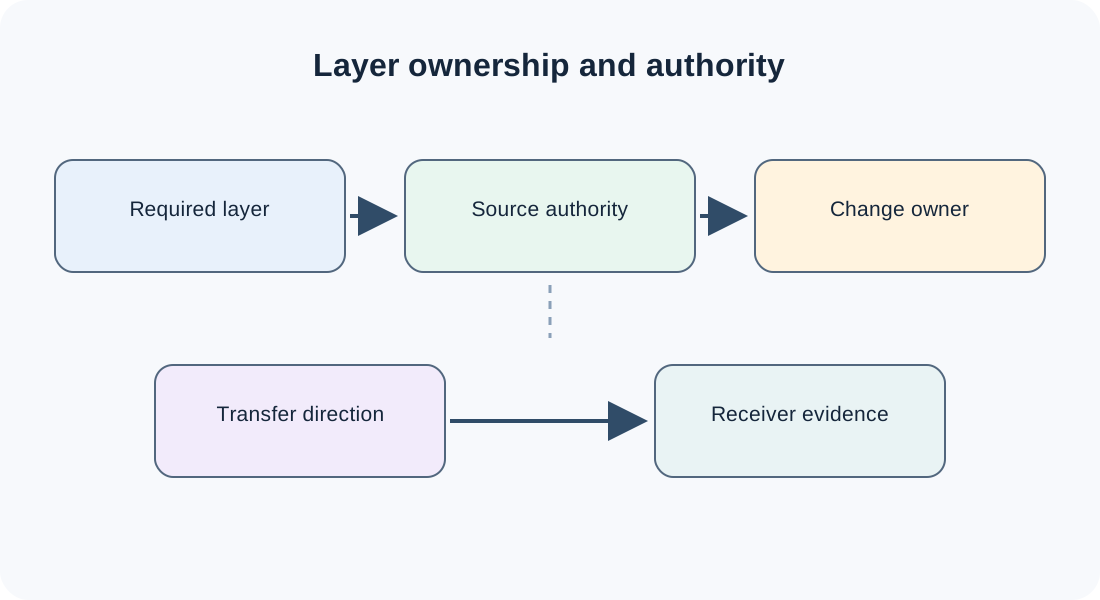
- Direction and authority: who owns the information, who may propose or apply a change, and which direction may it travel?
- Dependencies: which linked files, assets, references, or external systems must travel with it?
- Evidence: which comparison or human review can show that the requirement was met?
Do not use a standard’s list of capabilities as a substitute for this map. A representation can describe a concept without proving that a selected implementation writes it, reads it, or preserves it in a useful form.
Hand off the map to route research
The map is complete when each required layer has a purpose, a scope, a permitted-loss statement, and an acceptance method. It does not need a product or format decision yet.
Use CAD Interoperability Claims: Support, Conformance, Preservation, and Fitness for Purpose to phrase evidence claims precisely. For continuity, continue with Choose the Right Handoff Expectation: Delivery, Continued Work, Reference, Update, or Round Trip. A route should be considered viable only after its representation, implementation, and validation evidence answer the rows that matter.
Key points
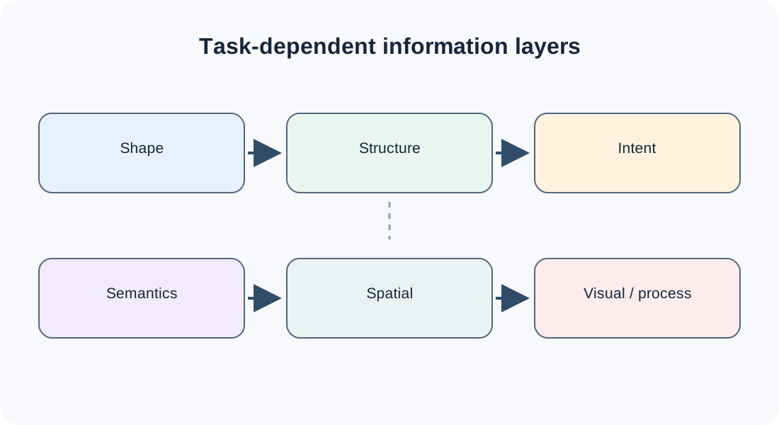
- Shape, structure, intent, semantics, spatial context, visual data, and production data are separate preservation questions.
- The receiving operation determines which layers are required.
- A visible result is not automatically editable, semantically meaningful, or production-ready.
- Record scope, dependencies, acceptable loss, and evidence for every required layer.
- Treat the map as a requirement for route research and acceptance, not as a compatibility claim.