An assembly can fail as a handoff even when every component opens and looks correct. The missing information may be the hierarchy that says which components form a subassembly, the occurrence that says where a reused part belongs, or the relationship that tells the receiver how the whole is organized.
The practical question is not “did the parts arrive?” It is “can the receiver identify and use the intended product structure for the next task?”
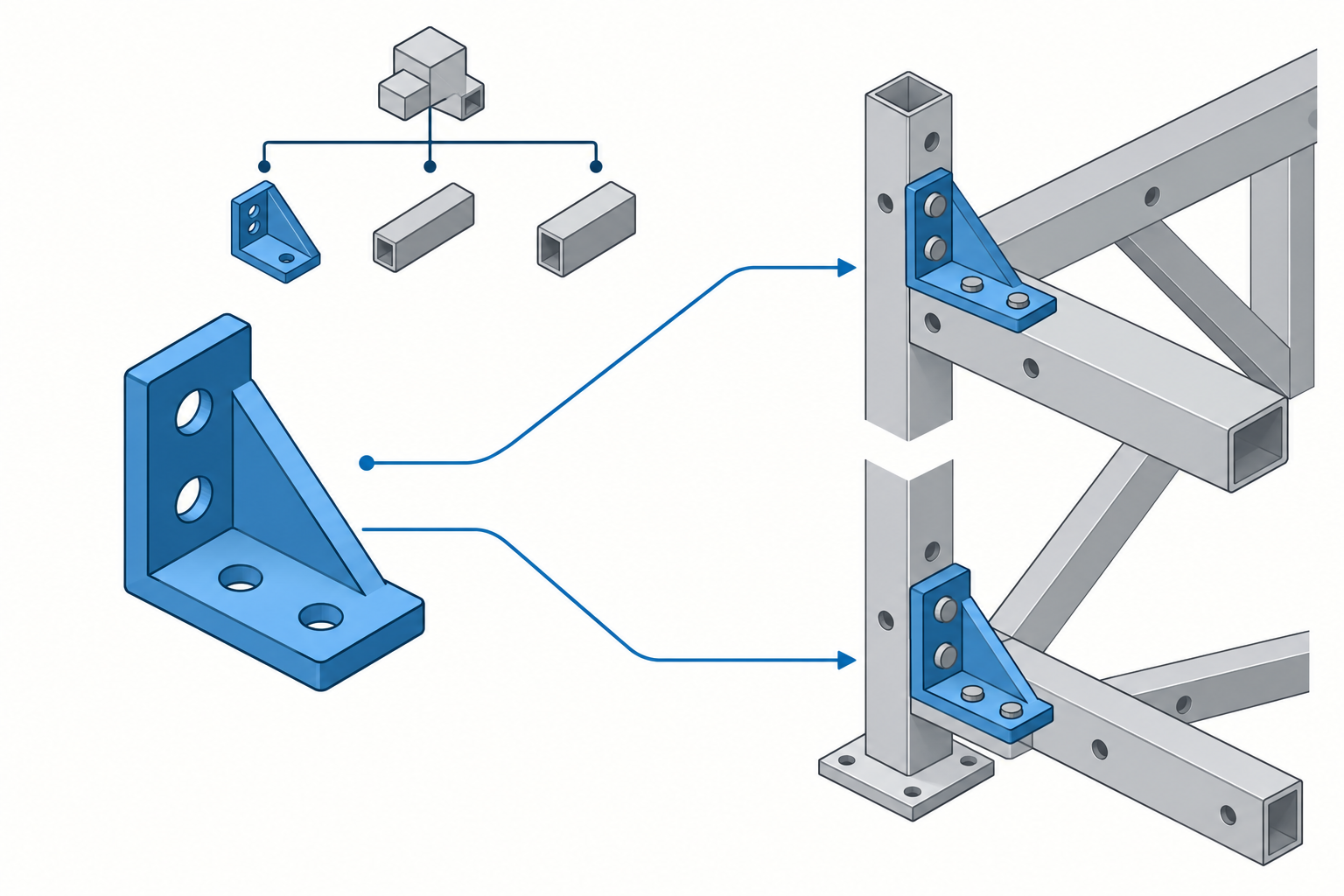
A collection of shapes is not automatically a product structure
An assembly usually combines several kinds of information:
- a component or part definition that can be used more than once;
- an occurrence or instance that places that definition in a particular context;
- parent-child relationships that form a hierarchy;
- placement or other context that locates an occurrence relative to its parent;
- relationships such as mates, constraints, or connections where the receiving task needs them; and
- configuration or variant context that says which design state is represented.
These terms are deliberately general. A product may call the reusable object a part, definition, component, or node, and the use of that object an occurrence or instance. Those labels are not portable definitions. Confirm their meaning in the source and destination systems before using them in an exchange requirement. A BOM or parts list is another view of product data: its rows and quantities may follow rules that differ from model membership. See how to reconcile BOM views with model membership before interpreting a row-count difference as a missing occurrence.
The distinction matters because the same definition can occur multiple times. If a transfer creates several independent copies of the geometry, the viewer may see the same shape in the right approximate places while losing the fact that the occurrences came from one reusable definition. A later replacement or update can then require manual reconstruction.
Bounded examples of structure models
The difference between shape and structure appears in several kinds of technical systems, but each example has its own scope.
Onshape documents an Assembly as a place where a hierarchical structure of part and subassembly instances is defined, along with how those instances move. Its documentation describes an Assembly that can instance another Assembly as a subassembly or instance a part directly. That is evidence about Onshape’s product model; it is not evidence that an export from Onshape preserves the same hierarchy in a different CAD system.
The export boundary matters too. Onshape can export an entire Assembly, subassemblies, or selected instances. For supported formats, exporting individual parts creates a ZIP whose members each contain one part; hidden instances can be included explicitly, while suppressed parts and instances are not included in Assembly exports. Onshape also states that downloaded data do not contain features or parametric history. These are sender-side scope and omission rules, not proof that a receiver will reconstruct the Assembly graph.
In IFC, IfcRelAggregates models a whole/part decomposition. Its RelatedObjects is a set, so the relationship does not imply an order among the parts. IFC also defines IfcRelNests as a different relationship whose related objects are a list and whose positions imply order. The distinction is useful when writing an acceptance requirement: matching the number of children is not enough if relationship type or order changes the receiving application’s behavior. The cited IFC 4.3.2 documentation is marked as under development, so the applicable release, view, and implementation agreement must be checked for a real exchange.
OpenUSD provides another bounded example. Its scene description uses a hierarchical namespace of prims, attributes, and relationships. References, variants, and native instancing express composition and reuse, while asset paths participate in external-file resolution. USD uses textual namespace paths rather than GUIDs for binding overrides. These are USD semantics, not a general identity model for mechanical CAD.
LOTAR also treats explicit assembly structure and product-structure archiving as deliberate information concerns alongside explicit geometry. Its product-structure validation specification describes separate detail and assembly nodes, selected critical attributes, child relationships, and validation properties. The specification’s scope is archive and product-structure validation; it does not certify the behavior of a generic CAD exporter.
JT v10 gives a format-specific example of structure beyond shape: its Logical Scene Graph can represent assembly branches, instance nodes, shared part nodes, external partitions, and positional transformations. The reference also requires measurement-unit context for interpreting numeric data. Autodesk Inventor documents different JT assembly output choices—monolithic, per-part, and full-shatter—as well as a single-file STEP assembly export. The choices describe representation and packaging, not equivalent receiver behavior; a handoff must record which option and file set was actually used.
Creo shows why a structurally named subassembly may still depend on its context. In Creo Parametric r12, placement geometry outside a subassembly can create an external dependency to the higher-level assembly and make standalone reuse difficult. If standalone reuse is the objective, investigate those placement references rather than accepting the subassembly because its tree is visible.
What a flat result can and cannot show
Suppose the receiving application displays one top-level item and a set of visible bodies. That proves only that the receiver can display something from the handoff. It does not by itself show:
- that the intended root object is present;
- that the original hierarchy has the same depth and parent-child relationships;
- that repeated occurrences remain linked to a shared definition;
- that placements, orientations, or relationship types are correct;
- that the selected configuration or variant is the one intended;
- that identifiers and revision context survived; or
- that referenced files are available and resolve to the intended versions.
It also does not show that the sender exported the intended selection. A hidden or suppressed component may have been omitted, or an assembly may have been emitted as individual part files rather than as one structure-bearing representation. Record the sender-side selection and packaging choices before comparing the result.
“Flattened” has to be interpreted in the system that defines the operation. For example, the OpenUSD referencing tutorial shows that a composed stage can be exported as flattened output. That changes the representation of composition, so a recipient that needs live references, overrides, or variant-selection behavior must test the flattened result against that purpose. Do not turn this USD example into a universal claim about every CAD format’s flatten or bind command.
A flat or copied result can still be the right deliverable. A supplier may need a stable snapshot rather than a live collaborative link, and a visualization or inspection task may not need editable structure. The decision is acceptable only when the lost structural behavior is outside the stated objective.
Write the structure requirement before choosing a route
Record the properties that matter to the receiver. A useful requirement includes:
| Property | Question to answer |
|---|---|
| Root | Which product, assembly, model, or project object must be the entry point? |
| Hierarchy | Which parent-child relationships and depth must remain? |
| Occurrences | How many occurrences are expected, and which share a definition? |
| Placement | Must each occurrence retain position, orientation, or a named relationship? |
| Relationship type | Are mates, connections, aggregation, nesting, or other relationships required? |
| Configuration | Which variant, configuration, or state is required at handoff? |
| Identity | Which names, part numbers, IDs, revisions, or quantities must be inspectable? |
| Dependencies | Which linked files, assets, project context, or external references must resolve? |
For a format with multiple sender-side structure options, add the chosen export version, grouping, and omission state to the requirement. A one-file result, a per-part file set, and a full-shatter package are not interchangeable acceptance targets.
Do not add a field just because it exists in the source system. Tie it to the receiving task. A fixed viewing snapshot may need a root, visible placement, and component count. A controlled update may also need stable identities, shared definitions, configuration context, and a tested update relationship.
Validate structure separately from shape
Use a structure-aware comparison after import or receipt. At minimum, compare the expected root, node or occurrence counts, hierarchy, placements, and required identifiers. Inspect the reference or dependency tree rather than relying on the viewport.
For archive-oriented work, LOTAR TS-9300-200-1 gives a bounded example of a validation property based on selected attributes and hierarchical relationships. Its assembly example incorporates each direct child’s selected identifier, revision, and quantity. The document treats the result as a consistency check, not as proof that the data’s meaning, geometry, or downstream usefulness is correct. If you adopt a similar check, define the attributes, normalization, ordering, and linked-file scope for your own exchange; do not present the LOTAR method as a universal importer test.
After structural comparison, perform the actual task that motivated the handoff. Open the expected root, expand the required levels, select the intended occurrence or configuration, reload any dependencies, and try the update, supplier, archive, or downstream operation. A structure that matches on paper but cannot support the receiving task is not an accepted handoff.
Key points
- Component shapes are only one layer of an assembly handoff.
- Definitions, occurrences, hierarchy, placement, relationships, configuration, identity, and dependencies have separate acceptance questions.
- A product-specific or schema-specific structure model is not proof of cross-system preservation.
- A flattened or copied result may be appropriate when the objective does not require live links, variants, shared definitions, or future updates.
- Sender-side export selection, suppression state, grouping, and units are part of the handoff record.
- Validate the structure against the receiving purpose, then validate geometry and other information layers separately.