Georeferencing is the relationship between a model’s engineering or project coordinates and a coordinate reference system used to describe location. It is not just an origin offset. A BIM exchange can overlay another model in one viewer and still lack the information needed to reproduce its position in a different project, system, or tool.
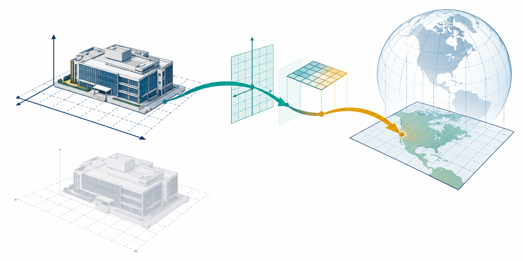
Keep the coordinate chain explicit
Describe the chain in layers:
- Object or model-local coordinates — where geometry is defined relative to a local origin.
- Project or engineering coordinates — the frame used by the design team, site, or coordinated project.
- Map or geospatial coordinates — the target coordinate reference system used for location outside the model.
- Vertical context — a height reference or vertical datum when elevation has a material geospatial meaning.
The coordinate-context article explains the local-to-project portion in more detail. Georeferencing adds the identity of the source and target reference systems and the operation that relates them.
A CRS name is not the whole operation
The OGC representation of a coordinate operation identifies a source CRS, a target CRS, an operation method, and method-specific parameters. Parameter units and the source-to-target direction matter. An identifier or a human-readable CRS name alone does not necessarily tell a recipient which operation, datum treatment, or parameters were used.
OGC uses “conversion” and “transformation” deliberately. A conversion operates between CRSs based on the same datum, while a transformation operates between different datums and can use empirically derived parameters with associated observational error. A dataset using a dynamic CRS may also need a coordinate epoch. These distinctions do not select the operation for a project, but they show why the operation type, parameters, accuracy context, and time reference can be material handoff data.
The correct operation depends on the project location, survey or control agreement, jurisdiction, and required accuracy. There is no universal origin, axis convention, unit choice, vertical datum, or conversion that is safe to prescribe without that context.
Make the operation reproducible
The same source and target CRS can have more than one applicable operation. Available choices can depend on the area of use and on local resources such as transformation grids. Record the selected operation and enough of its environment for another specialist to understand the choice:
| Record | Include |
|---|---|
| CRS and coordinate time | Exact source and target CRS, axis and unit context, vertical component when needed, and coordinate epoch where a dynamic CRS requires one. |
| Operation | Authority identifier or method, direction, ordered steps, parameter values, and parameter units. |
| Area and accuracy context | Area or extent for which the operation applies, plus the operation’s stated accuracy and the source of that figure. |
| Software and data | Transformation engine and version, CRS or operation database version, required grid-resource names and versions, and whether they were available. |
| Fallback | Whether a different operation or fallback was permitted and which one was actually used. Keep it distinct from the intended operation. |
The selected operation’s stated accuracy is not an independent measurement of the delivered BIM’s position. It describes the operation source’s accuracy context; a project still needs its own control, comparison method, and acceptance criteria. Likewise, matching the operation name does not prove that a receiver had the required grid resources or applied the same sequence.
The current stable PROJ documentation identifies the site as version 9.9.0. Its detailed operation-search page says that the algorithm explanation describes PROJ 8.0.0 and that results may depend on the PROJ database and version. Use it as an implementation-specific illustration of selection factors, not as an authoritative rule for choosing a project’s geodetic operation.
What IFC can represent
IFC 4.3.2 documentation separates the projected CRS from the map conversion. IfcProjectedCRS can identify the map reference system, including a recognized identifier or WKT when one identifier is not unambiguous. It can also carry geodetic and vertical datum context, projection, zone, and map units. For a three-dimensional geometric context, the documentation requires a compound CRS in which the geodetic and vertical datums can be identified unambiguously.
IfcMapConversion describes the relationship from the local engineering coordinate system to the underlying map coordinate system. Its documented operation applies a common scale to the three axes, a horizontal rotation, and translation through eastings, northings, and orthogonal height. The source also states that IfcMapConversion does not perform the projection from a geodetic CRS to a map CRS. In other words, the CRS identity and the engineering-to-map relationship are distinct parts of the declaration.
These are representational capabilities in a specified IFC documentation scope. They do not prove that a named exporter, importer, release, or viewer preserves and applies the values correctly.
The IFC documentation also separates operation identity from CRS identity: IfcCoordinateOperation names the source and target relationship, while IfcCoordinateReferenceSystem requires either a CRS name or well-known text. Geometric representation subcontexts inherit their parent’s spatial context and do not carry an independent coordinate operation. Multiple contexts for one project are expected to use the same operation and referenced CRS; a representation view or target scale is not a substitute for that consistency.
Minimum spatial handoff statement
For a reproducible handoff, record:
- the source frame and target frame;
- the source and target CRS identifiers, including the vertical component when material;
- the coordinate operation method, direction, parameters, and parameter units;
- local, project, and map units;
- axis orientation, up direction, and handedness where relevant;
- the origin or control relationship used to place the project;
- the IFC release and model-view scope when the delivery is IFC;
- the intended use and the aspects explicitly excluded; and
- the evidence that will be used to determine whether the result is spatially correct.
Do not use “georeferenced” as a substitute for those fields. If one is unknown, record the uncertainty and resolve it with the project’s responsible survey, design, or coordination authority.
Why visual alignment can mislead
A viewer applies a saved offset
A viewer may display a model at a convenient location or use a project setting that is not carried by the exchanged file. The overlay can disappear when the file is opened elsewhere.
Two models share an assumed origin
Two teams may call an origin “shared” while using different units, axes, rotations, or control points. Matching extents are not enough to establish the relationship.
Vertical meaning is omitted
Horizontal alignment can look correct while heights use different datums or an unexplained local elevation. Whether vertical context is required is project-dependent, but omitting it must not be hidden behind a general georeferencing label.
Map conversion is incomplete
An IFC file can identify a CRS while failing to state or preserve the engineering-to-map operation, or it can state a map conversion without proving that the receiver applied it. The schema’s ability to represent both does not resolve implementation behavior.
Before you call the model aligned
State the independent comparison that will establish spatial correctness, including the control or reference data, coordinates or features to compare, tolerances, and responsible reviewer. Formal acceptance execution belongs to the validation category; this article defines the information that acceptance must be able to interpret.
The safe conclusion after an import is therefore limited: “the model displays in the expected place in this context.” A stronger conclusion—such as correct project georeferencing—requires the declared chain and independent evidence.