Coordinates are numbers. Their meaning comes from the contract around those numbers: the unit, axis convention, frame, origin, and transformations that relate one frame to another. A transfer can preserve valid geometry while changing its scale, orientation, or location if that context is omitted or interpreted differently.
Geometry is not spatial meaning
A point such as (1250, 300, 0) is not self-explanatory. It could be millimetres from a component origin, metres from a project origin, or coordinates in a projected map system. The same vertices can describe different physical locations depending on the interpretation.
Treat these as separate items in an exchange declaration:
| Item | Question the recipient must be able to answer |
|---|---|
| Units | What does one coordinate unit represent, and do length and angle measures use the same conventions as the source? |
| Axes | Which direction is X, Y, and Z? Which axis is up? Is the frame right- or left-handed where that distinction matters? |
| Origin | What physical or logical point is (0, 0, 0)? |
| Frame | Is the coordinate local to an object, component, model, project, or world? |
| Placement | Which parent frame or placement gives the object its position and orientation? |
| Transform | What scale, rotation, translation, or other operation relates source and target frames, and in which direction? |
The OGC WKT standard describes coordinate reference systems and operations as representations that can identify source and target systems, an operation method, and method-specific parameters. It also explicitly leaves the way implementations read or write those strings to the implementation. That distinction matters: a representation can describe a relationship without proving that a CAD or BIM application carries or applies it.
The operation type can matter as well. OGC distinguishes a coordinate conversion between reference systems based on the same datum from a coordinate transformation between different datums. A transformation may use empirically derived parameters whose accuracy and observational error are relevant to the result. This is a reason to record the operation and its parameters, not only the names of the frames; choosing the correct operation remains a project-specific decision covered in the georeferencing article.
Do not assume that every frame operation can be composed by the same algebra. An OGC Testbed-18 engineering report explains that exact conversions through a common frame can be composed, but that a chain of geodetic transformations does not generally establish a suitable operation between the other two frames. Preserve the specified operation and direction in the handoff; do not derive a project transformation just by inverting and composing frame links. This is a specialist report analysis, not a normative rule change or a product test.
For a dynamic CRS, a coordinate epoch describes when the coordinate values are valid in that reference system. It is not necessarily the date the asset, survey, or scan was acquired. The OGC GeoPackage CRS WKT extension 1.1 allows an optional coordinate-epoch field alongside the CRS definition. That is a container-specific metadata example, not evidence that another format or a CAD/BIM receiver preserves or applies the epoch.
Local, project, and world frames
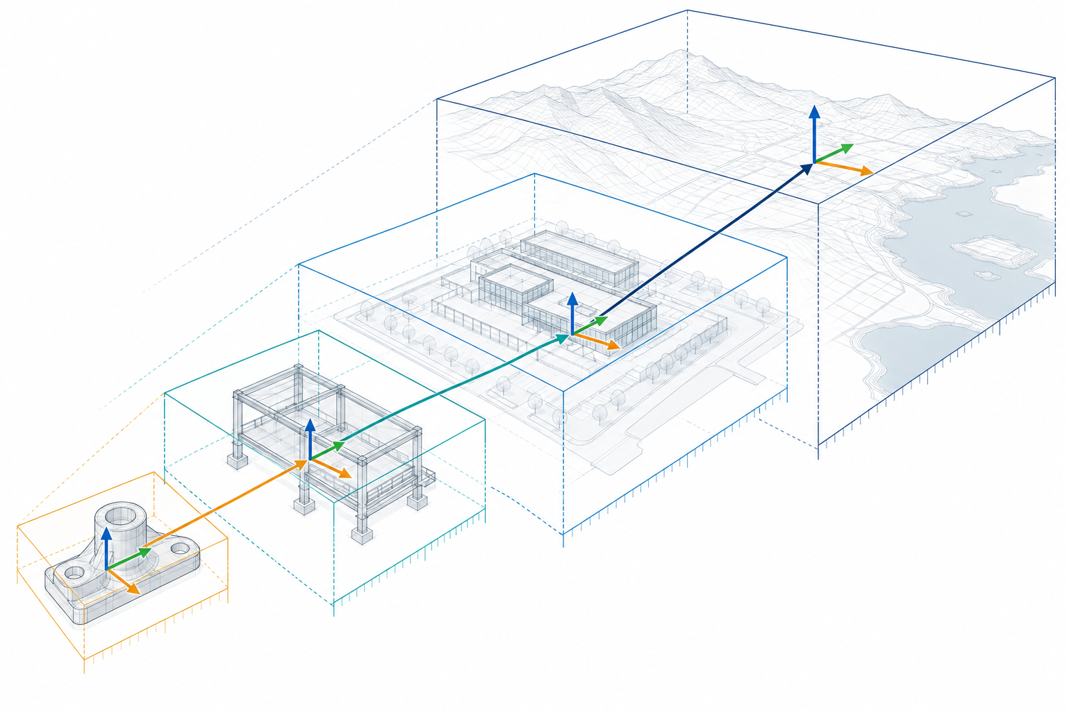
Design data commonly has more than one frame. A part may be modelled around its own origin, placed in an assembly frame, and then positioned in a project or world frame. A BIM object may be located through a chain of placements in a spatial hierarchy.
In IFC, IfcObjectPlacement establishes a product’s coordinate system. A placement may be absolute relative to the project world coordinate system or relative to another product’s placement. The referenced placement and the relative placement together express a relationship in the hierarchy. This is IFC representation semantics, not evidence that an exporter and importer preserved or composed the hierarchy correctly.
IFC also gives the coordinate operation its own identity. IfcCoordinateOperation relates a source CRS to a target CRS and can connect a geometric representation context with a real-world CRS; the CRS itself must be identified by a name or well-known text. The generated IFC 4.3.2 documentation used here carries an IFC4X3_ADD2 under-development label, so that documentation scope must remain separate from the official release status recorded for an exchange.
Representation subcontexts do not create independent spatial frames. In the cited IFC documentation they inherit the parent context’s world coordinate system, coordinate-space dimension, precision, and true-north context. When a project supplies multiple geometric representation contexts, their coordinate operation and referenced CRS must remain consistent. A view or target scale is therefore not evidence of a separate transform.
The useful question is therefore not “does the file contain coordinates?” but “can the recipient reproduce the path from each relevant local frame to the frame required for the task?” A flattened result may still be useful for viewing, but it has lost information if the recipient needs to move, update, classify, or coordinate the original hierarchy.
A practical handoff declaration
The following is a conceptual declaration, not a format-specific syntax. It makes omissions visible before a file is sent.
source_frame: component-local
target_frame: project-coordinate-system
length_units: millimetre
angle_units: degree
axis_convention:
  up: Z
  handedness: right-handed
origin:
  description: "Project control point P-01"
placement_relationship: "component-local -> assembly -> project"
transform:
  direction: source-to-target
  operations: "scale, rotation about stated axis, translation"
  parameters: "attached transformation record"
vertical_context: "state if height has a project or geodetic datum"
intended_use: "coordination reference"
known_exclusions:
  - "parametric history"
  - "application-specific constraints"
Do not fill a field with a guess merely to make the declaration look complete. If the source does not identify the axis convention, transform parameters, or parent placement, say so and treat the missing item as an exchange risk.
Common interpretation traps
Unit assumptions
Numeric values may be read in a default unit, while measure-valued properties may carry a different local unit or no explicit unit at all. IFC project units apply to geometric representation items and measure-valued data unless a local unit definition changes the applicability. A recipient still needs to verify how the chosen implementation consumes those declarations.
Axis and handedness changes
Swapping two axes or changing the up axis can make a model appear rotated or mirrored. A view that looks plausible from one angle is not proof that the coordinate convention is correct.
Hidden offsets
A large translation may be intentional—for example, a project placement—or may be an unexplained export offset. Record the reference point and the transform direction instead of describing the result only as “far away.”
Flattened placement hierarchies
Flattening a hierarchy can preserve displayed positions while discarding the relationships needed to update or reason about individual objects. Conversely, retaining a hierarchy without proving that the receiving application composes it correctly can preserve the wrong result just as consistently.
Before transfer
Record the source and target frame, length and angle units, axis and up conventions, origin, placement parents, transform direction and parameters, vertical context where relevant, and coordinate epoch when a dynamic CRS requires one. Record acquisition date separately. Identify whether the transfer is expected to preserve the hierarchy or only the displayed coordinates. Include exclusions such as editable history, structured BIM relationships, or georeferencing when they are not part of the delivery.
This declaration makes a later comparison possible. Formal spatial acceptance and independent comparison belong to the portal’s Validation, Exchange Control, and Long-Term Reuse coverage; a successful import or a visually plausible overlay is not, by itself, evidence that every item above survived.