A flat rigid-flex design and a folded integration model serve different purposes. Before transfer, name the task: electrical layout review, enclosure integration, assembly planning, or a supplier’s fabrication review. Do not treat a visible fold as proof of material behavior or manufacturability.
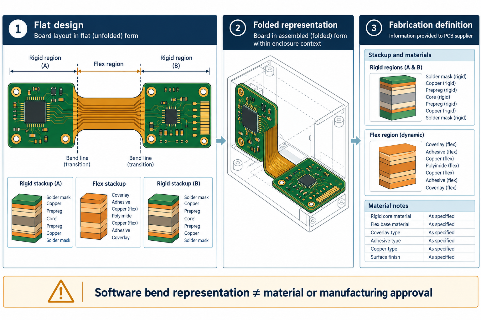
Record regions and state
Specify the source board revision and configuration, the rigid and flex regions, the stackup assigned to each region, and the required display or delivery state. Identify the bends and their sequence when that information matters to the receiving task. Record component position relative to the intended state, along with any features the receiver cannot represent.
Flat board definition ── region identity, local stackup, bend data ──> folded integration representation
          └──────────────── complementary fabrication definition ──> supplier review
This is a planning diagram: the two handoffs can use different representations and need separate checks.
In Altium’s documented CoDesigner workflow, the rigid-flex board is designed flat, with separate layer stacks assignable to regions. Bends can be applied for a folded display; the board is pushed to MCAD in a folded state, where bends may be suppressed for work on the model. The workflow checks outline and bending-area conditions on push, then checks whether bend radii can be represented as MCAD sheet-metal bends on pull.
These checks answer whether the geometry can be represented by that software workflow. They do not establish that a selected material can bend as modeled, that a supplier can manufacture the design, or that stackup and fabrication information are complete. The page’s version selector is not evidence of the add-in installed in a particular team.
Check the representation for the actual task
| Question | What to compare | What the comparison does not prove |
|---|---|---|
| Are the expected regions present? | Region boundaries and their assigned layer stacks | Material equivalence or electrical performance |
| Is the right state shown? | Flat or folded state, bend sequence, component orientation, and enclosure relationship | Physical bend feasibility or assembly success |
| Did the representation change? | Outline, flex regions, bends, thickness assumptions, and placed components | That every design property transferred |
| Is the data ready for fabrication? | Required fabrication files and supplier-defined stackup/material content | Supplier acceptance or production capability |
Ask the intended fabricator for its requirements and verify the resulting fabrication set independently. Keep a geometric fit check separate from a supplier’s material and process review. For board geometry and population, see the enclosure-fit guide; for package contents, see the PCB supplier package guide.