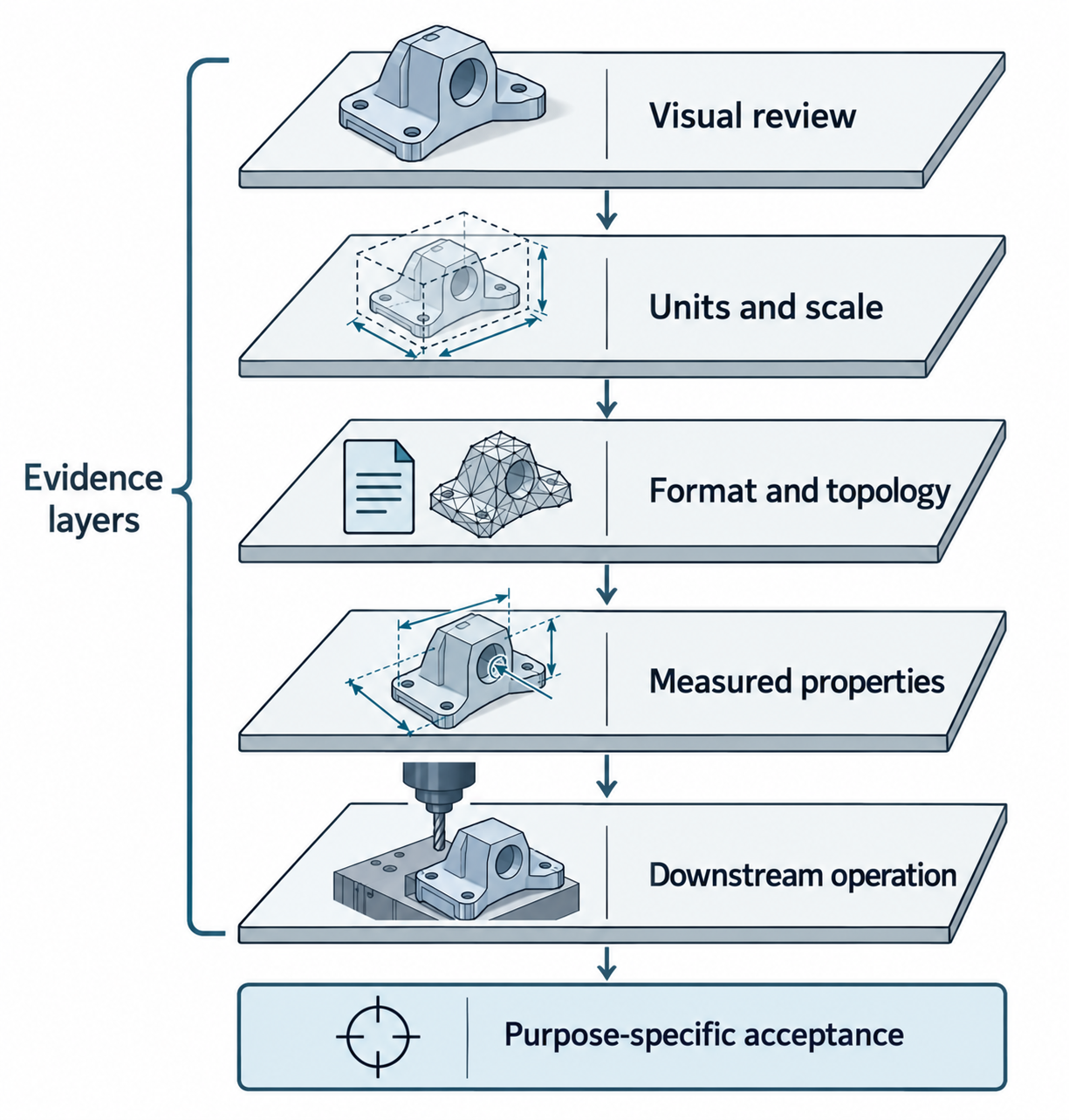
Validation is a decision about a purpose, not a single green check. A model can pass a visual review and fail a boolean, or match volume while containing a local gap. Define the receiving task first, then choose checks that expose the failure modes that matter.
Set the acceptance question
Write the question in a form another person can repeat:
Can the received representation support [operation] within [stated limit], using [specified units, version, and profile], while retaining [required information layers]?
Examples:
- Can the receiving CAD system perform the required cut or measurement on the imported solid?
- Does the mesh remain closed, oriented, and scaled for the intended additive process?
- Does the delivered point cloud retain the registration and uncertainty evidence needed for comparison?
- Does the visualization asset meet the required appearance and size without pretending to be editable CAD?
Do not let “accepted” mean “all information survived.” List what the check covers and what it leaves unproven.
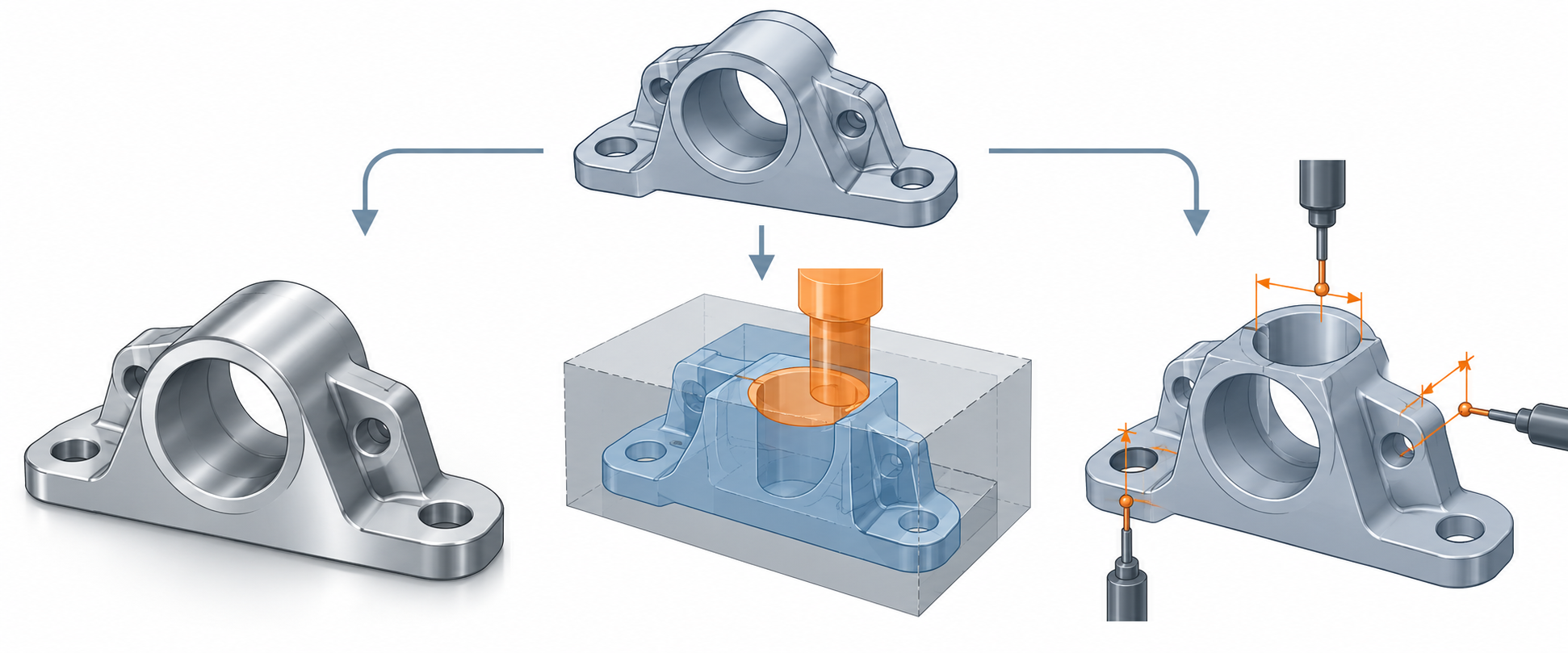
Use layers of evidence
| Check | What it can establish | What it does not establish |
|---|---|---|
| Visual review | Orientation, gross omissions, obvious scale or appearance problems | Exact geometry, local topology, units, editability, or task fitness |
| Unit and bounding-box check | Scale interpretation and gross dimensional consistency | Local surface deviation or topology health |
| Syntax or package check | Format structure, references, required parts, or declared profile conditions | Correct geometry or downstream usefulness |
| Topology/mesh health check | Selected closure, orientation, manifold, degeneracy, or kernel-validity conditions | A universal definition of validity or a task-specific production result |
| Source-versus-received properties | Agreement for the properties actually measured within an agreed tolerance | Unmeasured local defects, PMI, structure, editability, or every data layer |
| Downstream operation | Evidence that the receiver can perform the named operation on this result | Other operations, versions, models, or future edits |
Use multiple layers when the purpose demands it. A visual check is valuable, but it should not be the only check for a model that will be edited, measured, or manufactured.
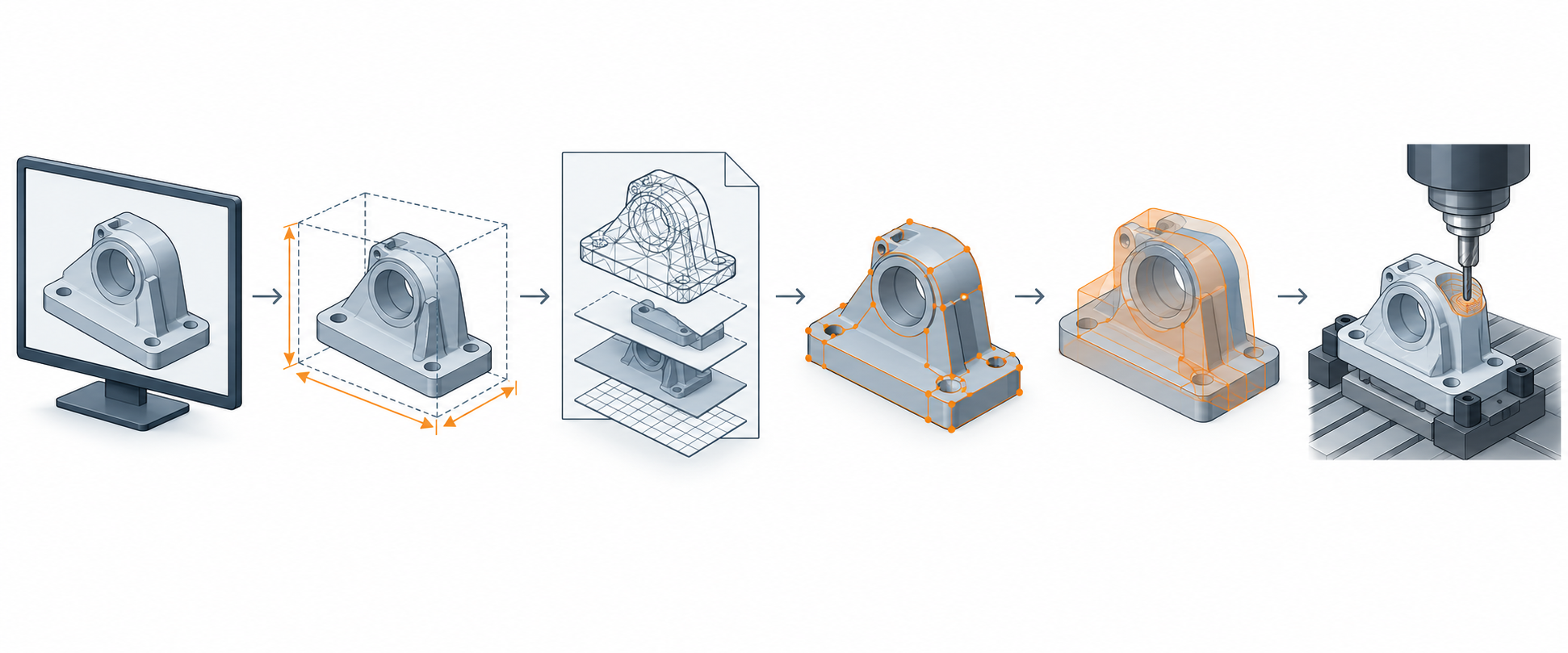
Record the comparison population and direction
A deviation value is meaningful only with its reference, alignment, units, direction, sample population, filters, and invalid-result handling. Different tools can report different quantities under the same label.
| Example | What the documented method compares | Limit to retain |
|---|---|---|
| Creo Parametric R12, Compare Part by Geometry | Builds a point cloud from the current part at a user-selected measurement spacing and compares the second part against it using a tolerance in part units | Sampled and directional; the help does not promise a symmetric or continuous surface bound |
| SHINING3D Inspect 1.5.0.9 | Compares aligned reference and measured models; point-cloud neighborhoods and mesh normal-line intersections use different local methods | A failed comparison-point creation produces invalid values, not a measured zero or a pass |
| Trimble Business Center Scan Inspection | Compares selected mesh/surface and point-cloud regions, with optional signed or absolute distances | A maximum-distance cutoff excludes points, and reports may contain only selected inspection points |
| Rhino 9 ThicknessAnalysis | Measures from analysis-mesh vertices through a solid to its other side | Vertex sampling and analysis-mesh density matter; this is not an independent-surface comparison |
Autodesk Fusion API PolygonMesh.compareWith |
Computes a signed distance for each node of the calling mesh to the closest point on another mesh, in centimeters | Directional node sampling; the method is marked Preview and does not define alignment, continuous coverage, or acceptance |
| CAx-IF STEP geometric properties and COPS, practice v4.6 | Receiver-calculated properties can be compared with source values; COPS adds sample points on individual faces | Requires comparable geometry scope and units plus an agreed task limit; face samples do not prove continuous surface agreement |
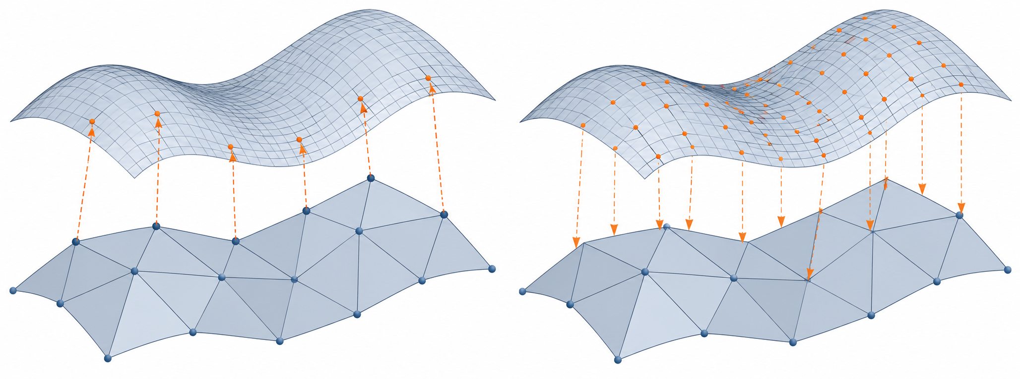
Sampling plans are part of the measurement basis. NISTIR 4897 describes a historical CMM study of sample plans for planar flatness against pre-specified tolerances. Its accessible abstract does not provide general sample counts or extend the result to freeform CAD surfaces.
CAx-IF’s geometric and assembly validation practice describes source-provided STEP values and receiver-recomputed values for selected properties such as volume, area, centroid, and COPS face samples. Property definitions and units must be comparable, and the pass limit must be agreed for the task. Aggregate values and sampled face points add different checks; neither establishes error between samples or a named translator’s preservation result.
STEP validation properties
NIST’s STEP File Analyzer and Viewer 5.41 describes validation properties as quantities computed by native CAD software to validate their import into another CAD system. The page says the Analyzer can report these properties, generate entity- and attribute-level spreadsheets, and check basic STEP syntax problems such as unresolved references and incompatible attributes.
The current NIST User Guide (Update 7) adds useful scope context: its report groups include geometric, PMI, assembly, annotation, attribute, and tessellated validation properties, and the report records property names, value types, units or exponents, and links to STEP entities. It also provides a view for AP242 tessellated part geometry. These are analysis outputs, not evidence that every property is present in a given file or that a receiving task will accept it.
The NISTIR 7897 guide gives a historical example procedure for geometric validation properties:
- Add the selected properties in the originating CAD system when exporting the STEP file.
- Import the STEP file into the receiving CAD system.
- Compute the same properties in the receiver.
- Compare the values using an agreed tolerance.
- Treat the exchange as validated only within the scope of the properties that are within that tolerance.
The guide names area, volume, and centroid as examples and preserves units or exponents with measured values. It also says validation properties are communicated through CAx-IF recommended practices rather than being part of ISO 10303 itself. The guide identifies itself as superseded by NIST AMS 200-6, so treat it as historical procedure evidence and verify current tooling and recommendations before relying on it.
Matching area, volume, and centroid does not prove every local face, edge, or topology condition. A property set is useful only when it is selected for the receiving purpose and the source and receiver calculate comparable quantities.
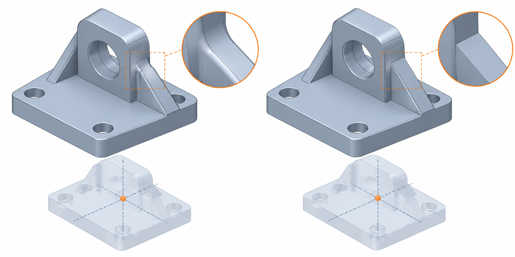
Format and kernel checks are bounded
Use representation-specific preflights as layers in the acceptance record. The official glTF-Validator checks glTF 2.0 syntax, schema, references, buffers, resources, and selected extensions, then emits a JSON report. The official 3MF Core specification requires package-contained manufacturing payloads and object-scoped mesh conditions; lib3mf exposes type-dependent object validity and typed package errors. An OCCT BRepCheck_Analyzer result is bounded to its kernel criteria. Each check can reveal a different failure, but none proves that a CAD exporter preserved the source, that a mesh is fit for fabrication, or that an untested destination operation will succeed.
Scan and point-cloud acceptance
For scan-derived data, add checks for the evidence that created the geometry:
- units and coordinate context;
- source or point-source identity when traceability matters;
- registration method, control or overlap basis, and residual/orientation uncertainty;
- point spacing or mesh resolution;
- acquisition and reconstruction limitations;
- the comparison method and task-specific tolerance.
The USGS 2025 Rev. A lidar specification is a bounded example of recording units, source IDs, and positional-accuracy verification. It is not a universal mechanical-CAD acceptance rule. NIST’s ASTM E2919-22 context supports treating orientation error and uncertainty as explicit scan evidence. The OSAC TLS document is an open-comment proposal focused on forensic-scene capture, so its guidance must remain qualified and cannot supply a finished CAD threshold.
Rhino 8’s PointDeviation command is one bounded way to compare selected points or point clouds with target geometry. It reports point count and distance statistics, but some measured object types use analysis-mesh vertices, and selected objects and filters affect the result. Record the sampling basis and settings, then set any pass limit from the receiving task; the command does not validate registration or establish a universal acceptance threshold.
Write the acceptance record
Record enough context that someone can reproduce the decision:
- source file and received file;
- source and destination applications and versions;
- format/profile/version and required extensions;
- units, coordinate or transform context, and import/export settings;
- representation tested: exact, B-rep, tessellated, mesh, points, or derived surfaces;
- checks performed and tools used;
- source and received values, comparison tolerances, and results;
- topology or mesh exceptions and repair operations;
- downstream operation tested;
- information layers intentionally excluded or not proven;
- decision: accepted for the stated purpose, accepted with restrictions, or rejected for re-export, repair, or another route.
If a check fails
Use the failure to narrow the next decision:
- Recheck units, coordinates, profile, version, and import settings.
- Determine whether the failure is syntax, representation, topology, precision, registration, or task acceptance.
- Preserve the original and compare an alternate representation or route.
- Repair only with a recorded intervention and a new comparison.
- If the result cannot meet the original purpose, communicate a narrower accepted use rather than a general compatibility claim.
For repair boundaries, see geometry repair after translation. For topology and attribute checks, see topology and model health and mesh fidelity.