Choose an exchange representation from the information the receiving task must use. “The file opens” and “the object looks recognizable” are weak tests: neither tells you whether the receiver got exact surfaces, usable topology, an adequate approximation, or only a display mesh.
Start with the receiving task
Write the requirement as a short chain:
source environment → representation → destination environment → downstream task
Then name the information layer that must survive. Examples include:
- analytic curves and surfaces for continued CAD work;
- a solid or shell with usable topology for operations in a receiving kernel;
- a bounded faceted approximation for visualization;
- a mesh with normals and texture coordinates for a rendered asset;
- a closed, correctly oriented mesh for an additive workflow;
- measured points with registration and uncertainty information for inspection or reverse engineering.
If you cannot name the required layer, a compatibility answer is premature. A destination may support a format while still receiving the wrong representation for the job.
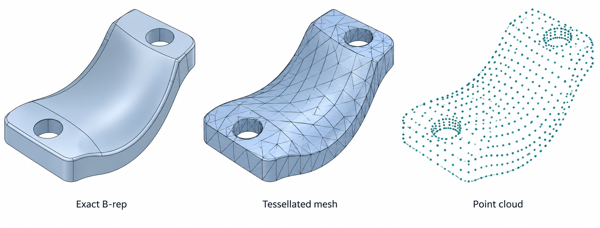
Three representation families
The STEP AP242 interoperability overview distinguishes exact shape, tessellated shape, and parametric representation. Those are capabilities of a representation model, not a promise about every exporter, importer, or route.
The comparison below turns those broad representation families into six reader-facing delivery forms: it separates runtime and manufacturing mesh packages, includes point clouds as a related handoff form, and treats subdivision control data separately from its evaluated surface. It is not a one-to-one list of AP242 representation categories.
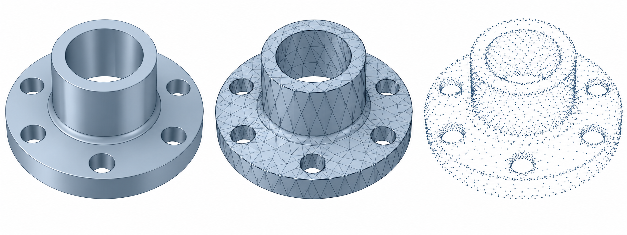
The standards layer is broader than any one transfer route. ISO 10303-42:2025 describes generic geometry, topology, precise solids, B-rep, tessellated geometry, and the association of tessellated geometry with exact geometry. ISO 10303-242:2025 describes a managed mechanical-engineering protocol that includes several geometry-model types, 3D scan data, and combined shape representations. Those scope statements tell you what a standard can describe; they do not show that a selected profile, exporter, importer, or destination preserves every listed representation. Record the edition, profile, direction, and implementation when those details matter.
CAx-IF’s recommended practice for AP242 tessellated geometry also distinguishes representation rules by AP242 edition and lists accuracy-parameter types for tessellated data. Its Release 1.1 reports that those accuracy parameters had not been implementor-tested when published. Their presence describes metadata capability, not measured received error or support on a selected route.
| Representation | What it can express | Good starting point for | What it does not prove |
|---|---|---|---|
| Exact CAD geometry or B-rep | Curves, surfaces, and the relationships used to describe an exact shape | CAD exchange where surface/solid operations or measurable geometry matter | That a particular translator will preserve topology, tolerances, or editability |
| Subdivision control surface | A control cage plus topology and evaluation rules that define a limit surface | A receiver that can interpret the same scheme, creases, boundaries, and interpolation | That a refined cage or polygon-mesh import evaluates to the intended surface |
| Tessellated shape | A faceted approximation; some representations can retain topology associated with the facets | Controlled display, lightweight review, or a task whose error bound is known | That the receiver has the original analytic surfaces or feature history |
| Runtime mesh | Vertex positions, triangle indices or other primitives, and optional attributes such as normals, tangents, UVs, and colors | Rendering and interactive asset delivery | CAD units, B-rep semantics, design intent, or correct use by a particular consumer |
| Manufacturing-oriented mesh package | Mesh vertices and triangles plus package, unit, and extension semantics | A bounded additive handoff when the receiving process supports the package | Printer suitability, dimensional accuracy, or support for every extension |
| Point cloud | Sampled coordinates and, depending on the format, related point attributes | Scan delivery or measurement workflows | A reconstructed surface, watertight solid, or CAD-ready model |
The boundaries are important. A mesh is not simply a low-resolution B-rep, and a point cloud is not automatically a mesh. If the destination needs an exact surface or a valid solid, a visually smooth triangle model may be the wrong deliverable even when it renders well.
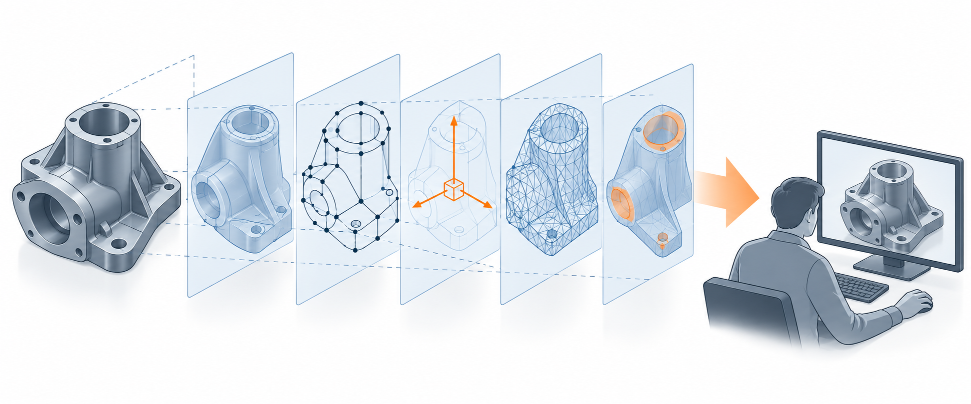
A subdivision cage is also not the evaluated surface. OpenUSD’s mesh schema can describe polygonal meshes and subdivision surfaces with scheme, crease, corner, boundary, hole, and face-varying rules; its default scheme is Catmull-Clark, so a polygon mesh intended to remain unsubdivided must declare none. OpenSubdiv distinguishes refining the cage from tessellating the limit surface: refined cage points generally do not lie on that surface. This is schema and algorithm behavior, not proof that a named exporter or receiver preserves or evaluates those rules. For the handoff decision and checks, see subdivision surfaces and evaluated meshes.
Why “looks right” is not enough
A tessellation can approximate a surface while hiding the analytic curves and surfaces that created it. A mesh can also omit or regenerate normals, lose UV sets, contain degenerate triangles, or use a scale that the receiver interprets incorrectly. A point cloud can contain useful samples while leaving registration, acquisition uncertainty, and reconstruction quality unresolved.
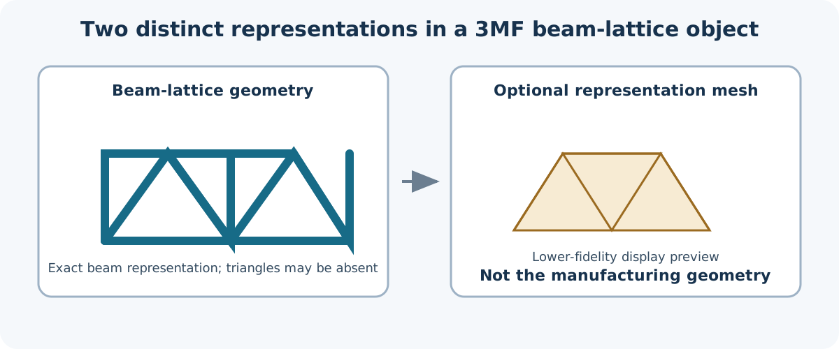
For a manufacturing-oriented package, mesh validity and package validity are separate questions. The 3MF Core specification defines a ZIP/OPC package, a model coordinate-space unit, and mesh conditions for model and solidsupport objects. The Beam Lattice Extension 1.2.0 adds a distinct exact beam representation that can be present without triangles; its optional representationmesh is only a lower-fidelity preview and must not be used for manufacturing. The package must declare the b extension required, and the recipient must support it to interpret the lattice geometry. These are format rules, not evidence that a particular producer, recipient, or manufacturing process supports the extension.
A bounded receiver example
The SOLIDWORKS 2025 help documentation illustrates why the receiving application and option set belong in the exchange record. It documents reading STEP AP203, AP214, and AP242 through 3D Interconnect, choosing how assembly structure is imported, selecting file-specified or document-template units, and enabling import diagnostics. It also says that a STEP file containing FACETEDBREP is imported as a graphics body by default, with Load Geometry available to import it as BREP data.
Those options describe SOLIDWORKS 2025 receiver behavior. They do not establish what a particular source exporter placed in the file, whether the received BREP is healthy, or whether it is fit for editing, fabrication, or inspection. Verify the actual file and the selected options.
Choose without overpromising
Use this sequence before exporting:
- Define the required information. Say whether the destination needs analytic shape, topology, a display approximation, a mesh payload, points, or a package for a specific process.
- Define the acceptance operation. Examples are a CAD boolean, a measurement comparison, a render, a slice preview, or a controlled downstream test.
- Select a representation and profile. Record the format, application protocol or extension set, version, units, and relevant export settings.
- Check the destination’s intake behavior. Format support means the application can attempt an import; it does not establish preservation or usefulness.
- Compare the received result with the purpose. Use topology checks, attribute inspection, geometric properties, or task-specific tests as appropriate.
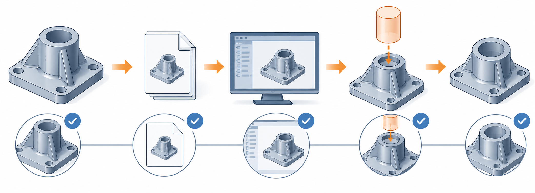
Avoid an unqualified “lossless” label. Preservation depends on the source data, selected representation and profile, translator, destination, version, and purpose. A successful visual review can support a visual purpose; it cannot by itself prove exact geometry or editable design intent.
Quick preflight
Before sending the handoff, record:
- the source model’s representation and units;
- the information layers that are required and those intentionally excluded;
- the format/profile/version and any required extensions;
- the producer and receiver versions and relevant import/export options;
- the expected topology or mesh conditions;
- the geometric or task-specific checks that will decide acceptance.
For the receiving-side checks, see topology and model health and validate a geometry handoff. For mesh attributes and resolution, see mesh fidelity.
Sources and scope
The STEP AP242 and ISO sources describe representation or protocol scope. The glTF and 3MF sources define their own payload and package semantics. The SOLIDWORKS example is limited to the documented 2025 intake behavior. None of these sources is an end-to-end test of an arbitrary source-to-destination route.