Precision is not one number. A model’s kernel tolerance, a mesh’s surface deviation, a coordinate unit, a numeric representation, a point spacing, and a measurement uncertainty answer different questions. An exchange is controllable only when those questions are stated separately.
Define the requirement first
Start with four inputs:
- the smallest feature or distance that matters;
- the maximum deviation the receiving task can accept;
- the operation that will decide acceptance;
- the units and scale context understood by the receiver.
“Use a high-quality export” is not an acceptance requirement. A CAD boolean, a printed part, an inspection comparison, and a render may need different representations and checks. Manufacturing and measurement limits must come from the applicable process owner or specification; generic geometry advice cannot supply them.
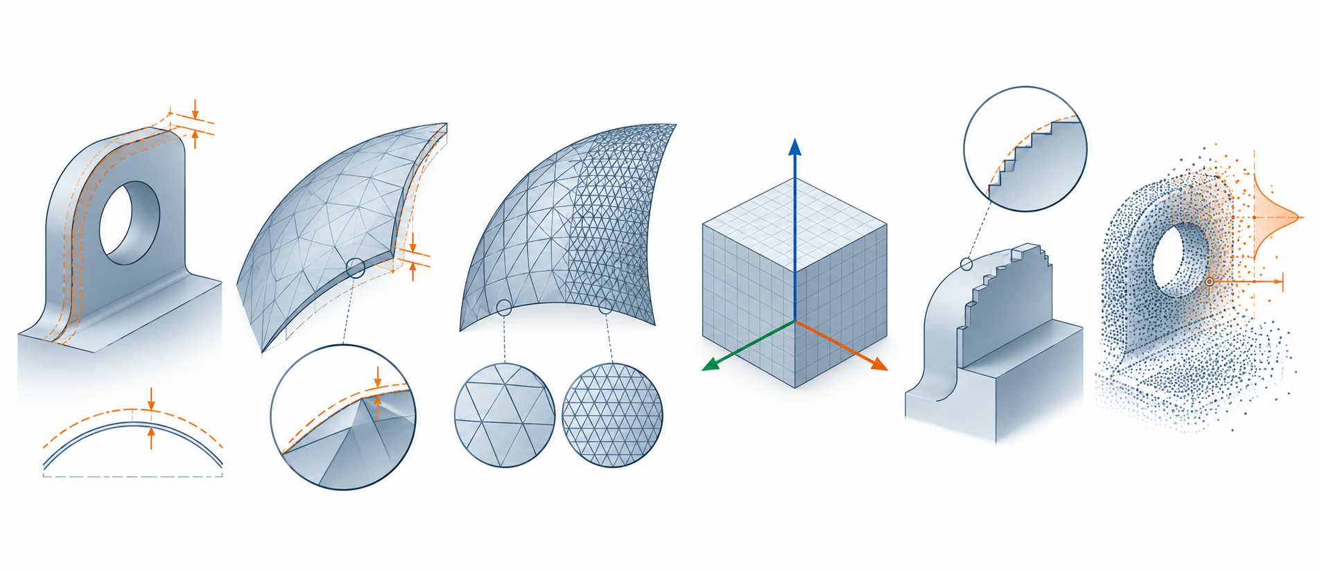
Keep precision layers separate
| Precision layer | What it describes | What to record |
|---|---|---|
| B-rep or kernel tolerance | How a geometry kernel treats coincidence and local gaps | Kernel/tool, units, local or global values, and the operation for which the value matters |
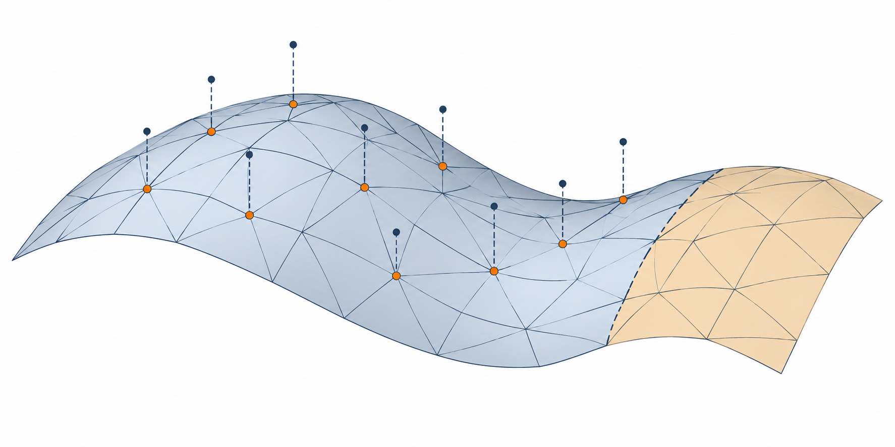
| Tessellation deviation | How far a faceted surface may depart from an exact surface | Chordal or other stated error measure, settings, and whether the exporter actually reports a bound |
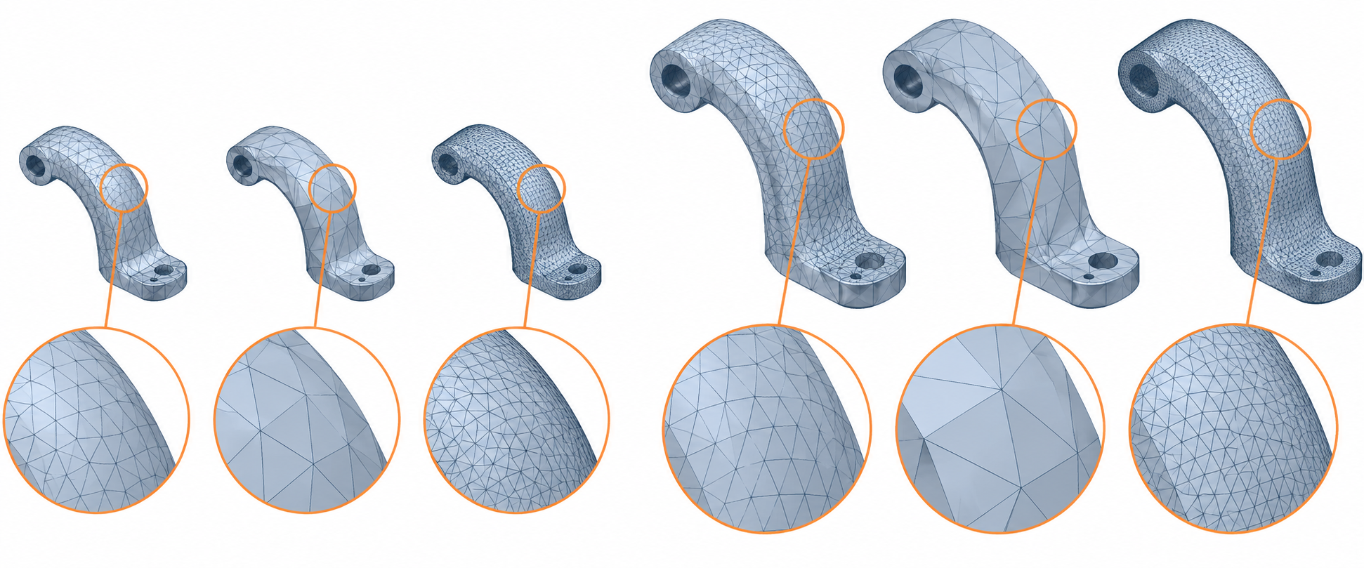
| Mesh density | Sampling density or triangle size | Density rules, feature protection, simplification, and task-specific acceptance |
| Coordinate unit and scale | The numeric interpretation of positions | Source unit, file/profile unit, receiver setting, and a known-size check |
| Numeric precision | How coordinates and calculations are represented | Format and application limits where material; do not confuse digits with geometric accuracy |
| Scan point spacing and uncertainty | Acquisition sampling and measurement confidence | Scanner context, resolution/distance, registration, reported uncertainty, and reconstruction effects |
Open CASCADE’s current ShapeAnalysis_ShapeTolerance reference demonstrates why a model tolerance should not be collapsed into one value. It can compute minimum, maximum, and average stored tolerances and find sub-shapes within a range or over a threshold, with scope for vertices, edges, faces, shells, or all shapes. That is an OCCT inspection capability, not a universal tolerance definition or a correct threshold for another kernel.
OCCT’s current BRepCheck_Analyzer can also report an invalid tolerance value as one of its shape-status conditions. That is evidence of a defect under OCCT’s implemented checks, not a selection of the tolerance that should replace it. The correct value still depends on the model, receiving operation, units, and acceptance purpose.
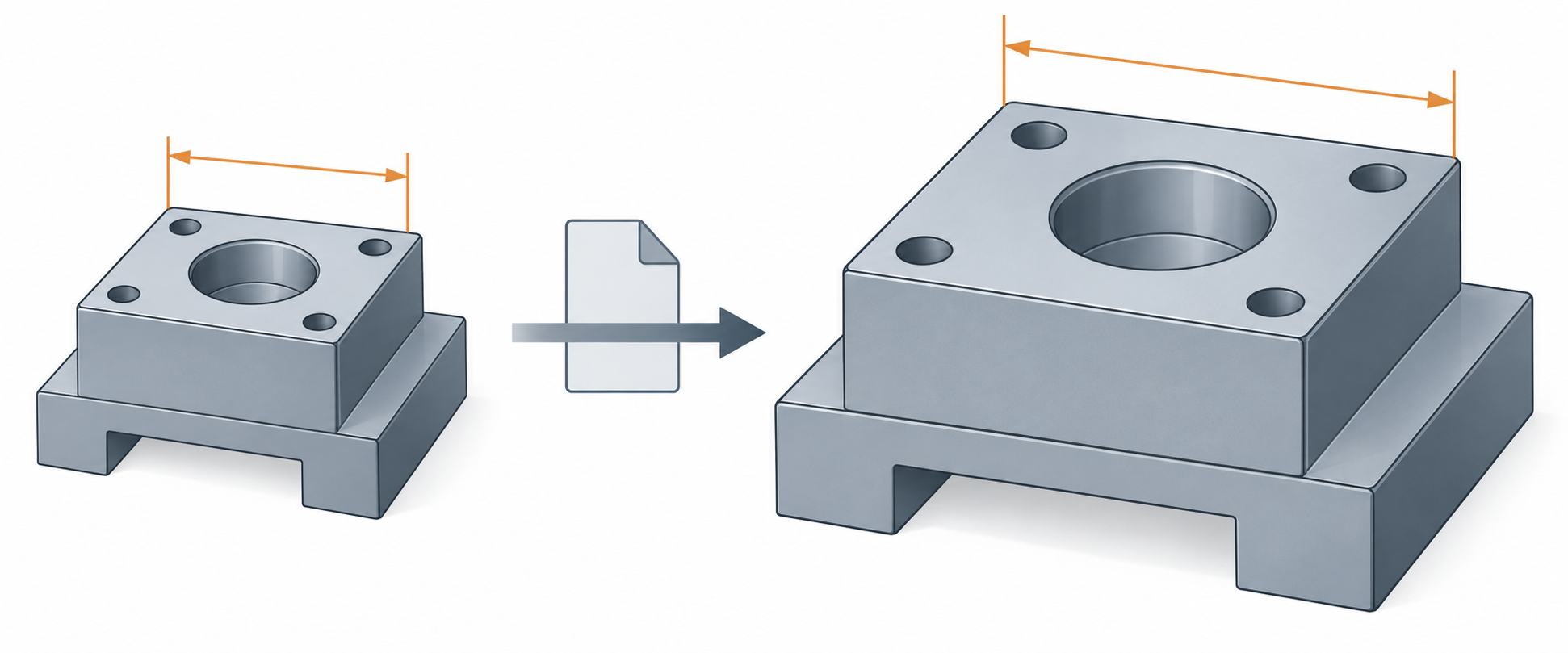
Units can change the shape you receive
Record units at both ends of the transfer. The 3MF Core 1.4.0 specification defines a model coordinate-space unit, defaults it to millimeter, and lists micron, millimeter, centimeter, inch, foot, and meter as valid values. That tells you how a 3MF model declares its coordinate space; it does not guarantee that an unrelated consumer interprets every package correctly.
The glTF 2.0.1 accessor table describes POSITION as “unitless XYZ vertex positions,” while its coordinate-system section defines all linear distances in meters. Read together, core glTF model-space distances use the meter convention; the accessor wording does not leave the model’s linear units unspecified. glTF does not record the source CAD unit or any producer-side conversion history, so document conversions made during export and check a known dimension after import. A visually plausible asset can still have the wrong physical size if that conversion or receiver interpretation is wrong.
SOLIDWORKS 2025 documents a receiver-side choice between using the file-specified unit and the document-template unit for neutral-file imports. The selected option must be part of the test record. A unit mismatch can change bounding-box dimensions by a factor while leaving the model recognizable.
Inventor 2026 illustrates how a repair tolerance should be treated as a controlled change boundary. Heal Errors uses an Allowable Change value and can preview the extent of repair. Its Refit Face workflow defines a Maximum Tolerance as the maximum deviation allowed when generating a replacement face, recommends starting small and increasing slowly, and allows a repair attempt to be undone. These controls are product-specific; none supplies a universal export or acceptance tolerance.
AutoCAD 2026 exposes FACETERDEVSURFACE for mesh conversion from solids or surfaces through MESHSMOOTH. Its documented initial value is 0.0010; smaller values produce more faces and less deviation from the source surface, with slower performance. This describes a product setting, not a measured error bound for the exported or received mesh. The initial value is not a portable default.
The measurement domain behind a meshing option also matters. Rhino 9 documents maximum angle as scale-independent, while minimum and maximum edge length and maximum edge-to-surface distance depend on model scale. Its edge-to-surface measure uses mesh-edge midpoints; that value is not a continuous maximum over the whole mesh. The Jagged seams option meshes joined surfaces independently and can leave naked edges, so inspect shared boundaries after conversion. Record the setting, its measurement domain, and the received result rather than treating the option name as an achieved error bound.
Geospatial point-cloud deliveries add another bounded example: the USGS 2025 Rev. A lidar specification prefers consistent horizontal and vertical units, says mixed units are not recommended and must be noted in spatial metadata, and expects source identity and reported accuracy controls. Those are USGS lidar-delivery requirements, not mechanical-CAD tolerances.
STEP AP242 tessellated representations can describe accuracy-parameter types such as angular and chordal deviation, maximum edge length, and edge-shape ratios. CAx-IF’s 2019 practice says these parameters had not been implementor-tested at publication. Treat them as format metadata, not proof that a selected implementation used the values or achieved the stated deviation; compare the received geometry separately.
Do not rely on defaults
Defaults vary by producer, consumer, representation, version, and downstream purpose. Before export, capture:
- source application and version;
- model units and coordinate context;
- exact, tessellated, mesh, or point representation;
- format/profile/version and extension set;
- tessellation, simplification, or tolerance settings;
- receiver import settings and expected interpretation;
- the acceptance measure and its allowed tolerance.
If the software does not expose an error bound, say so. Do not convert a quality preset or an “accurate” label into a numeric guarantee.
For STEP exchanges, NIST’s current STEP File Analyzer User Guide (Update 7) groups validation properties into geometric, PMI, assembly, annotation, attribute, and tessellated reports. It describes comparing properties written by the originating system and recomputed by the receiving system within an agreed tolerance. Area, volume, and centroid are examples, not a universal property set, and the result is bounded to the properties actually written, recomputed, and compared.
An export-to-check workflow
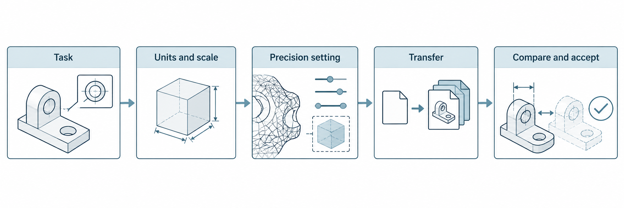
- Name the purpose. Identify whether the result is for editing, display, additive work, fabrication, measurement, or another task.
- Choose the smallest relevant feature. Use it to set the representation and required precision conversation.
- Set and record units. Include a known dimension or reference object that can be checked after import.
- Set tessellation or precision controls. Preserve the option names, values, and version; include a stated deviation if the tool provides one.
- Import with recorded receiver settings. Do not silently accept a template unit or default profile.
- Compare the result. Check scale, bounding dimensions, selected geometry properties, topology, and the downstream operation.
- Record exclusions. A geometric match does not establish structure, feature history, PMI, materials, or other data layers.
For a mesh, include attribute and resolution checks from mesh fidelity. For source-versus-received geometric comparisons, see validate a geometry handoff.
Subdivision evaluation and deliberate mesh reduction change what is being compared. See subdivision surfaces and evaluated meshes and mesh reduction and remeshing before choosing a tolerance or interpreting a comparison.
What cannot be generalized
There is no universal tessellation tolerance, triangle density, scan resolution, or CAD-kernel tolerance that guarantees an acceptable result. A geospatial accuracy class does not become a mechanical-part tolerance, and a matching volume does not prove local surface or topology health. Use the requirement of the actual destination task and preserve any unresolved applicability as an explicit limitation.