“Editable” is too broad to select a safe CAD exchange route. A model that can be opened, measured, or moved is not necessarily a model whose sketches, constraints, feature relationships, or source-authoring decisions can be changed. Define the next change first; then choose a representation and test that representation against the change.
An editability ladder
The following ladder is a planning vocabulary, not a standard classification or a strict quality ranking. A lower level can be exactly right when it satisfies the downstream purpose.
- View and measure. The recipient can inspect the representation and take measurements. This may be enough for reference, quoting, or visual coordination, but it does not establish a modifiable model.
- Retain a live reference. The destination can monitor or consume an associated source and receive updates. The source system may remain the authority for changes; an update relationship is not the same as destination-side editing.
- Change the boundary representation directly. A boundary representation (B-rep) describes a solid or surface through its faces, edges, and topology. Direct editing changes selected geometry without requiring recovery of the source feature sequence. It can be effective for a bounded change, but it does not prove that source parameters or constraints survived.
- Edit recognized or reconstructed features. The destination identifies candidate features or a user rebuilds selected portions as destination-native features. Parameters or sketches may then be editable, but the result is recovered control, not automatically the original feature graph.
- Edit the source authoring definition. The source environment, or a demonstrably equivalent native representation, remains the authority for feature history, sketches, constraints, equations, configurations, and dependent relationships. This is the strongest claim and requires route-specific evidence.
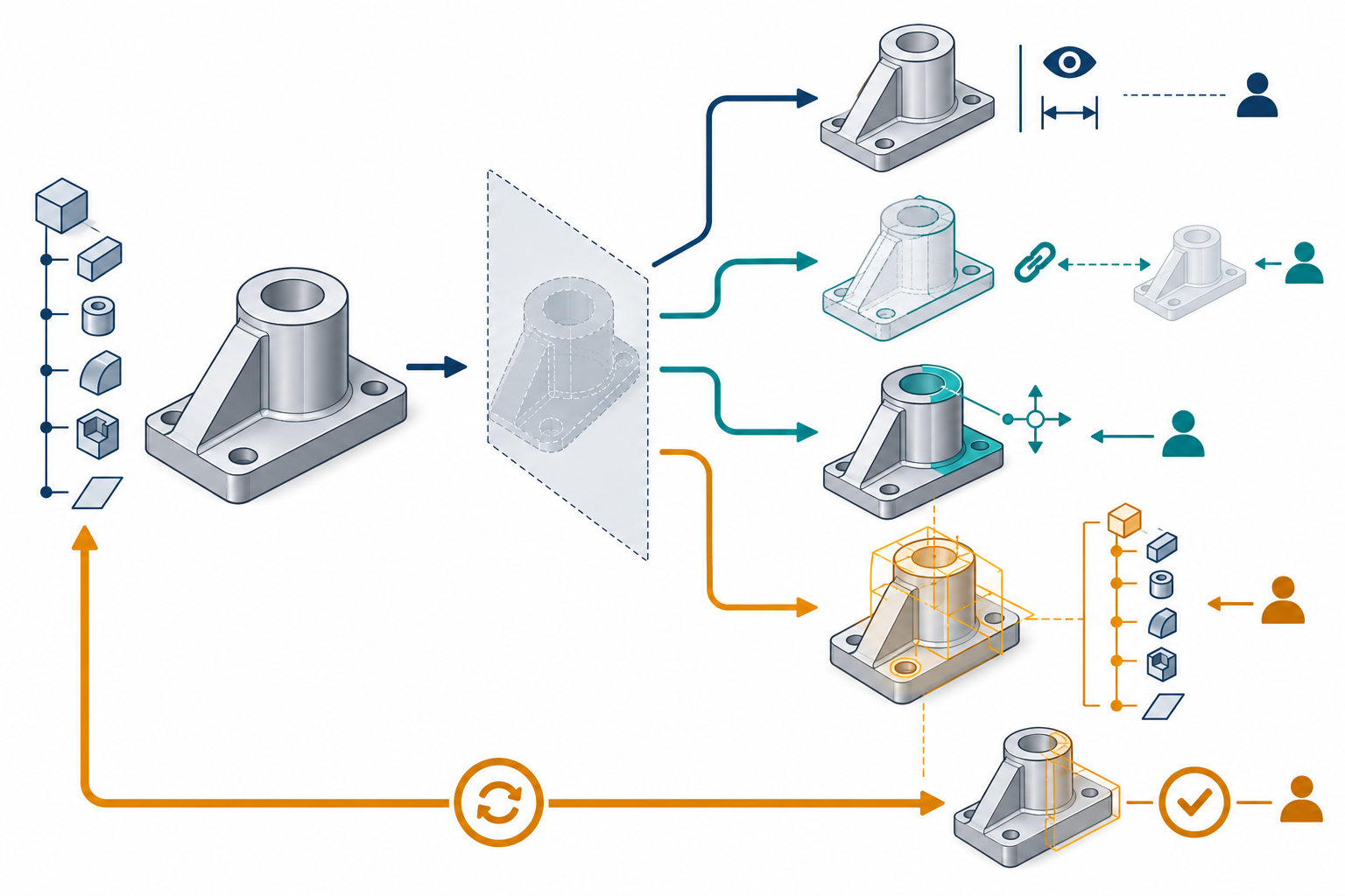
The boundary between these levels matters. Autodesk describes Inventor Direct Edit as manipulating the size, shape, or location of geometry, including imported base parts. That is useful destination-side control, not evidence that the imported model’s original history was reconstructed. Similarly, Creo describes Feature Recognition as a semiautomatic operation on imported B-rep models; supported candidate types and geometry checks do not establish source-history equivalence.
Product modes are part of the claim
The receiving product’s modeling mode can change what “editable” means. Autodesk Fusion distinguishes Parametric Modeling Mode, which records features and relationships in a timeline, from Direct Modeling Mode, which does not capture parametric features and relationships. Imported CAD starts with design history disabled by default; Fusion does not automatically recreate the source timeline. Find Features can recover some supported geometry as editable Fusion features, but this is partial recognition rather than source-history recovery. In the documented workflow, run Find Features in Direct Modeling Mode, then switch to Parametric Modeling to record subsequent Fusion operations in a new timeline. A direct-mode result or a Base Feature inside a parametric design remains a different claim from a fully reconstructed authoring definition.
Onshape gives the complementary warning: imported CAD may arrive without parametric history, as separate surfaces or parts, or with faults. Its direct-edit tools can still make a bounded change, but that result should be classified as destination-side control rather than source-history continuity. The product and release context belongs in the acceptance record.
What “design intent” might mean
Write down the information behind the change you need. Depending on the model, it can include:
- dimensions, tolerances, parameters, equations, and units;
- sketches, constraints, reference geometry, and dependency relationships;
- feature order, feature types, names, suppression rules, and rebuild behavior;
- configurations, family or variant definitions, and assembly context;
- annotations, materials, manufacturing rules, and other semantics required alongside the editable shape.
Not all of these need to survive for every task. A supplier may only need to move a mounting face and preserve a watertight solid. Another supplier may need to change a constrained layout repeatedly and produce a family of variants. State the required layer instead of treating “the model” as one indivisible thing.
Standards can describe representation capabilities without prescribing receiving-system behavior. ISO 10303-108, for example, covers parameter and constraint representation but excludes procedural history, constraint-solving methods, and post-transfer editing behavior. The presence of a parameter or constraint representation therefore does not establish that a selected translator or destination application will expose native-like editing.
ISO 10303-55 adds a separate procedural and hybrid representation scope for construction sequences, current-result associations, design rationale, and suppressible operations. That scope still does not establish that a selected file profile or receiving product implements the representation or rebuilds it equivalently. Treat standard scope, implementation support, and demonstrated edit behavior as separate evidence layers.
The requirement brief
Capture these fields before choosing a route:
| Question | Example of a useful answer |
|---|---|
| What must change? | Increase the hole diameter, move a mounting pattern, or produce three controlled variants. |
| Who owns the change? | The source designer, the receiving supplier, or both under an agreed handoff. |
| How often will it change? | Once for a quotation, periodically as the source evolves, or repeatedly during design. |
| What is the acceptable representation? | Directly edited solid, recognized features, constrained sketches, or source-native history. |
| Must source updates continue to arrive? | No; one-time delivery, or yes with a live reference and a defined update owner. |
| What dependencies matter? | Assembly placement, external references, configurations, PMI, materials, or manufacturing data. |
| Which releases and options are involved? | Exact source and destination releases, file type/profile, import mode, and relevant translator settings. |
| What proves acceptance? | A named change test, resulting dimensions and geometry, rebuild status, downstream output, and saved route context. |
This brief prevents a common mismatch: selecting a linked reference when the recipient needs independent editing, or selecting converted geometry when the source team still needs update authority. It also makes an honest “rebuild required” conclusion possible.
Carry critical intent when the history is unavailable
When future changes depend on why dimensions or features relate, pair the model with a short, project-specific intent note. For each important area, identify the geometry with a view or other reference the receiver can confirm, state the controlling dimension or constraint, explain the intended relationship and rationale, and name required variant behavior. Mark which information is present in the model and which is explanatory handoff material.
Ask the receiver to map the note to the imported geometry and test a representative change. Feature mapping, persistent names, and constraints can fail or differ across systems; a note or annotation does not become an executable constraint automatically. Treat this as a communication aid for the project, not a standard interchange schema. Keep annotations selective because excessive markup can clutter the model.
Treat successful opening as a weak signal
Opening a file proves only that the destination accepted enough of the package to create a view or model. Visual similarity does not prove feature control. A single face move does not prove constrained edits, assembly behavior, update persistence, or downstream output. Test the change that motivated the exchange and retain the conditions under which it passed.
Carry the result into route selection
Use the requirement brief with continuity strategies and the recovery options. For input-specific choices, see scan or mesh to editable CAD or IFC reference and native conversion. Then apply the editability acceptance tests. A good conclusion names the source, transfer mechanism, destination, release and options, required information layers, performed change, and remaining limitations. It does not promise that an extension is “fully editable” in the abstract.
Key points
- Define the change and the authority for that change before selecting a format.
- Separate reference updates, direct geometric edits, recovered features, and source-definition editing.
- Parameters and constraints in a representation are not proof of procedural history or receiving-system behavior.
- Accept editability only within a tested source–route–destination–task scope.